
Circuit breakers are common electrical devices in all applications, starting from home distribution panels to medium and high voltage switch gears.
I made a deep searching about circuit breakers, and I found some important questions you should know. Let’s answer these questions.
Table of Contents
What is Making and Breaking Capacity of CB?
Breaking capacity
The breaking capacity of a circuit breaker refers to its ability to interrupt an electrical current under both normal and fault conditions. It is essentially the maximum current that a circuit breaker can safely interrupt without causing damage to itself.
There are two main types of breaking capacity:
- Rated Breaking Capacity (Ics): This is the maximum fault current that a circuit breaker can safely interrupt without sustaining damage. It is typically expressed in kiloamperes (kA) or megavolt-amperes (MVA).
- Short-Circuit Breaking Capacity (Icu or Icn): This is the maximum prospective short-circuit current that a circuit breaker can safely interrupt. It takes into account the worst-case scenario of a short circuit occurring in the system. Short-circuit breaking capacity is usually higher than the rated breaking capacity.
It’s crucial to choose a circuit breaker with an appropriate breaking capacity for the specific application and electrical system it will be protecting.
If a circuit breaker is subjected to a fault current beyond its breaking capacity, it may fail to interrupt the current properly, leading to arcing, overheating, and potential damage.
When selecting a circuit breaker, it’s important to consider the system’s fault current levels and choose a breaker with a breaking capacity that exceeds those levels. This ensures reliable protection and safe operation of the electrical system.
Making capacity
The making capacity of a circuit breaker refers to its ability to withstand and close onto a circuit under specified conditions.
It is essentially the maximum prospective (or peak) current that a circuit breaker can safely close and make the circuit without sustaining damage.
The making capacity is a critical parameter, especially during the closing operation when the contacts of the circuit breaker come into contact with each other.
Similar to breaking capacity, making capacity is expressed in terms of current and is often denoted as the “making current” or “short-time withstand current.”
This specification is important to consider when selecting a circuit breaker for a specific application.
When a circuit breaker closes onto a circuit, there can be a surge of current due to factors such as inrush current or the system’s transient conditions. The making capacity is designed to handle these high current conditions during the closing operation.
It’s important to note that the making capacity is typically lower than the breaking capacity of a circuit breaker.
The breaking capacity is related to the ability to safely interrupt a circuit during a fault, while the making capacity is focused on the initial closure of the circuit.
When selecting a circuit breaker, engineers and electricians need to consider both the making and breaking capacities to ensure that the breaker can reliably operate in the specific conditions of the electrical system it is protecting.
Which one is higher, making or breaking capacity?
The making capacity of the breaker is always greater than the breaking capacity.
When the circuit is closed back after the shock recovery or fault recovery, a high value of current passes through the circuit breaker and the peak value of this current is much higher than the breaking capacity.
But, this current is just a surge and the current comes down to a normal value after some instance.
The reason for Making current is higher than the breaking is because, the Making current is the “peak” value, while the breaking capacity is an “RMS” (root mean squared) value.
Conclusively, The Making Capacity of a circuit breaker is higher than its Breaking capacity.
What is anti-pumping relay in circuit breaker?
Anti-pumping relay in the circuit breaker is used to safeguard the circuit breaker from multiple shutting commands.
If we issue another closing order after the breaker has been closed, the breaker or the closing coil connected with the mechanical parts may get damage.
To prevent these repeated commands, the panel maker wires these circuits appropriately in the breaker shutting circuit itself.
The anti-pump relay is nothing more than a NO contact, which means that while the circuit breaker is closed, the relay is in the NO position, and when the circuit breaker is open, the relay is in the NC position.
Difference between a feeder and a circuit breaker
A feeder is a network of wires connected by supports (towers/poles) that deliver electrical power/electricity to the distant consumer/beneficiary end of an electrical supply system.
A circuit breaker is a safety mechanism used at a power supply substation from which a feeder emerges to serve a specific region.
A circuit breaker activates in the event of a failure detected by a relay in a specific feeder, protecting the public/property and transformers from unanticipated events.
Difference between a latching relay and a lockout relay
A lockout relay is commonly used to prevent a system from returning to normal operation by opening a series of contacts that must be manually reset.
This is used when it is judged important to have someone physically present to inspect the system’s condition before resuming normal operation.
A latching relay is utilized when the relay must maintain its functioning condition while not being activated.
To restore or reset system functionality, this sort of relay may be reset electrically or manually. These were most commonly employed in relay reclosing.
Why a circuit breaker needs maintenance?
Breakers require maintenance, just like all other electrical devices, to be in a ready condition to do what it should do, protecting the electrical equipment.
Breakers, like other electrical equipment, require preventative maintenance on a regular basis.
Don’t allow your costly electrical equipment to degrade as a result of carelessness. Regular inspection and service may detect and solve problems, saving thousands of dollars of downtime and costly repairs.
I have written a detailed article about Electrical Maintenance, you can find it here for more information.
Does Voltage Matter on a Circuit Breaker?
Circuit breakers don’t trip due to overvoltage, the voltage does not matter on the circuit breaker tripping. Circuit breakers are not a voltage sensing device, It only can sense current.
The main reason for the independence of the circuit breaker from the voltage is that it is not connected to “ground” wire so, both the ends/ terminals have the same potential.
On the other hand, the voltage rating of the circuit breaker is an important parameter to consider, you should always use a circuit breaker with the same voltage of the circuit or even higher.
If you choose a lower voltage than the circuit voltage, then the breaker body, will not be able to bear the line to line voltage, and the body (insulation) will break down, causing a short circuit.
Can I Use an AC Circuit Breaker for a DC circuit?
Nope! Never use AC breaker in a DC circuit because, when the breaker trips, it produces an arc.
In the AC system, the fact that the current goes zero 50 or 60 times per second helps in arc extinguishing.
On the other hand, the DC current has a constant value. It does not go zero, because it does not have any frequency to shift the current from the peak amplitude to the zero value of current.
This constant value makes arc extinguishing harder in the DC circuit than AC one. In case of a fault, DC current will not oscillate (change polarity) and keep flowing through the AC circuit breaker for a longer time. As a result, the AC circuit breaker will meltdown.
So, conclusively, we can say that the AC circuit breakers can not be used for the DC current.
Difference Between Isolating Switch and Circuit Breakers
Isolating switches and circuit breakers are both power interrupting and circuit control electrical devices.
The main difference is, the isolating switch is a manual isolation device, while circuit breaker is an automatic protection device.
Let’s get in to some details.
Isolating Switch
A Switch is an electrical device that toggles the electrical state manually. Basically, the electrical switches control the flow of the electrical current within the circuit to make maintenance or for any other reason.
To control the electrical current flow manually, switches are the best and very reliable to use. The establishment and the disbanding of the circuit are dependent upon the state of the switch.
The user has a full control to turn the switch ON or OFF. We can use switches in our daily life circuits to turn ON or OFF our simple machines/devices, the simplest form of switches is the light bulb switch.
Circuit Breaker
The Circuit breaker is a safety electrical equipment. It is used to protect the “internal circuitry” of the devices. Generally, it is an overcurrent protection device.
The circuit breaker automatically shuts the power OFF in case of any, abnormal situation i.e overcurrent, earth leakage and short circuit.
| Circuit Breaker | Switch |
| Switches toggle the state of electricity connection | Circuit breakers, “breaks” the circuit when needed. |
| Switches are placed for the simple carrying out of functions | circuit breakers are for “safety and protection” purposes. |
| While switches can’t be work automatically. | You can use circuit breakers to manually turn OFF and, ON power. |
- Some people call a circuit breaker a “safety switch” which is not an absolute truth.
Can I use Switch as a Circuit Breaker?
Nope! You can’t use an isolating switch instead of a circuit breaker because, the circuit breaker is an automatically protection device. While the switch is just a general-purpose manually controlled isolation device.
In case of any fault, the switch does not have the ability to protect the circuit. While the circuit breaker senses the fault and “breaks OFF” the connection by cutting the power being supplied to the device.
While the converse is true. We can use the circuit breaker as a switch in the places where the toggling of the state is not very abrupt and periodic.
If you use a switch instead of a CB, this may cause the device to get damaged and the circuit to heat up, insulation to decrease and as a result a short circuit which may lead to a fire.
The purpose of the circuit breaker is not switching on and off, the circuit breaker is mainly a protection device for electrical loads and circuits.
If you need a switching on and off method for a load, you can combine the use of CB and an isolating switch. The CB protects the circuit and use the switch for switching purposes.
Why is the circuit breaker connected in series?
Circuit breakers are typically connected in series with the load for several important reasons:
- Protection of the Load: The primary function of a circuit breaker is to protect the connected load from overcurrents, short circuits, and other electrical faults. Placing the circuit breaker in series ensures that it can monitor the current flowing through the circuit and interrupt it in the event of a fault, thereby preventing damage to the connected equipment.
- Isolation of the Load: Circuit breakers provide a means of isolating the load from the power source. When a circuit breaker is open (in the off position), it physically interrupts the flow of current to the load. This is important for maintenance, repairs, or troubleshooting, as it allows workers to safely work on or inspect the load without the risk of electrical shock.
- Control of Power Distribution: Placing circuit breakers in series allows for effective control over the distribution of electrical power. By opening or closing the circuit breaker, one can control the flow of electricity to specific loads, enabling selective shutdowns when necessary.
- Easy Identification of Faults: When a fault occurs in a circuit, the circuit breaker helps in locating the fault. By isolating different sections of the circuit and testing them one by one, it becomes easier to identify the specific area where a fault has occurred.
- Compliance with Electrical Codes and Standards: Electrical codes and standards often mandate the use of circuit breakers for safety and regulatory reasons. Connecting the circuit breaker in series is a common practice in line with these requirements.
While circuit breakers are primarily connected in series with the load, there are also cases where they are connected in parallel for redundancy or to enhance reliability in critical applications.
In such configurations, each circuit breaker may serve as a backup for the other, providing an additional layer of protection. However, the series connection remains the standard practice for most electrical systems.
Can you connect two circuit breakers in parallel?
When 2 circuit breakers are connected in a parallel connection, the current flow through them becomes lower. But this connection is usually not appreciated.
The main reason behind it, is that the circuit breaker “breaks” the circuit if the current flow is too high.
When 2 circuit breakers are connected in a parallel combination to the same device or to the same system, if the first circuit breaker trips and cuts the connection through itself in case of overcurrent, the 2nd circuit breaker allows the current to flow, it’s not necessary to trip too, (if have more rating than the first one or if it is not as sensitive as the first).
This results in damaging the device or the system for which the first circuit breaker was set.
There is no problem in setting 2 circuit breakers of the same rating in the parallel combination.
The rating matching is a tricky and not-recommended method if done at the time of wiring.
The rating matching is an ideal method if done in the manufacturing unit during the manufacturing of the parallel circuit breakers. Still, it is not much recommended.
Can I use 2 Single pole CB instead of one double pole?
No. We should not use 2 single pole breakers instead of one double breaker.
The main reason for this limitation is that the system will not be safe anymore.
The double circuit breaker opens the circuit for two mechanically coupled poles and the power is cut to both lines (legs) simultaneously.
While for two single pole breakers, the simultaneous cutting of both lines is nearly impossible.
The main purpose of safety of a system or a device depends upon the cutting of power at the immediate moment of short circuit or overcurrent.
Another reason is that is not recommended due to the rating of 2 “different rated” circuit breakers.
An exception:
There is an exception in this case. The exception is that if the double pole circuit breaker was used as a safety switch for two different circuits, replacement of a double pole circuit breaker with 2 single pole circuit breakers is possible.
In this case, we won’t need to interrupt the power supply of one circuit due to failure in the other “independent” circuit as far as each circuit breaker fulfills the safety requirements (current value) of its own individual circuit.
In fact it should be designed as two single pole circuit breakers from the very beginning.
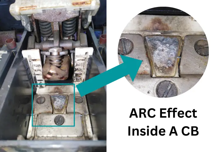
What causes a circuit breaker to explode?
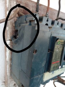
A circuit breaker can explode or catch fire due to the following reasons:
- A fault that exists between two adjacent phases or between one or more phases and ground can be the reason to explode the breaker.
- If the upstream device(s) can not limit short circuit amperage and is exceeded by the breaker before it can clear the fault, it may explode.
- It is also necessary to consider the voltage rating of these devices. If a device has a maximum voltage and its service voltage is higher than a major fault, it will explode.
- During a short, the circuit breaker cannot shut off the current, resulting in fires and explosions.
- In the case of an oil breaker, when the oil level is too high to make the circuit breaker more reduced, oil buffer space can cause the explosion of the circuit breaker when to short-circuit or fault occurs.
- If the oil level is too low, the circuit breaker contacts may not be soaked in oil and fail to extinguish the arc when the contacts are open, producing fire and explosion.
- Insulating oil impurities. It’s possible that the circuit breaker will flashover internally and explode as a result.
- Hydraulic or pneumatic pressure is too low and can cause an explosion.
- In case of the SF6 circuit breaker, if gas is too low, the circuit breaker arc quenching ability is reduced or even extinguished the arc, thereby causing the circuit breaker to explode.
Why lubrication is important in circuit breaker?
By properly lubricating circuit breaker components, you reduce friction and wear between moving surfaces, especially metal-to-metal moving surfaces; you reduce or prevent corrosion and rust; you repel pollution; and prevents heat accumulation.
High voltage circuit breakers need the rapid action of complicated mechanical assembly to function properly. As a result, important components of these systems, such as bearings, must be adequately lubricated to ensure appropriate motion.
A circuit breaker is electro-mechanical device which has both mechanical and electrical parts.
Mechanical parts should work properly to ensure the breaker will act perfectly in case of faults and short circuits. One of the most important things to consider is lubricating its parts.
You should follow the manufacturer’s instructions and procedure to ensure the best practice when lubricating the CB.
You should also use the recommended lubricant, and follow the lubrication schedule. Never over lubricant the circuit breaker, this may cause its closing time to increase.
What is circuit breaker condition monitoring?
By monitoring the condition of the circuit breaker, fault location and a pre-alarm can be determined. To determine these circuit breaker conditions, some parameters are to be selected.
The selection of appropriate diagnostic parameters depends on the overall effectiveness, accuracy, reliability and cost of measuring the parameters.
These are the series of parameters that are chosen, and corresponding methods can be used with various degrees of monitoring complexity:
Contact resistance measurement:
Measuring the contact resistance determines the condition of the Circuit breaker’s main and arcing contacts.
If due to any fault, the resistance of the circuit breaker varies from the normal value, the phase voltages and currents will differ. Such change in voltage leads to unnecessary losses, and the CB becomes less reliable.
Contact Erosion Analysis:
Arcing depends on wear and tear on contacts. This may lead to a shortening of the contact. This result leads to a decrease in the time difference between the operation of nominal and arcing contacts.
There is a specified amount of time interval in which current should be transferred from nominal contact to arcing contact.
Delay time:
The open and break time of CB should be within the prescribed normal limits. The increased delay time means the CB takes more time to switch states.
As a result, the arcing may last longer, and there will be more losses.
Phase current:
The current across a phase is monitored, which gives the breaker status. Abnormalities in any of the phases can be detected through phase current.
Absence or fault in any phase of the three-phase line will increase current in other phases. This increased current can be detected using a current transformer.
A higher amount of current than the usual value for a longer period can also lead to CB damages.
Phase voltages:
Measuring phase voltages helps in determining the phase faults as well as in monitoring the CB faulty conditions.
Phase voltages were measured using a Potential Transformer placed on CB contacts’ incoming and outgoing sides.
Any phase fault can be detected as the voltage across the phases is monitored continuously.
Contact Temperature measurement:
An increase in resistance of contacts, increase in voltage, or any faulty condition may lead to an increase in the temperature of CB.
This unnecessary increase of temperature results in more arcing spark and other abnormalities, leading to damage to contacts. The temperature sensor is placed at the contacts for temperature measurement.
What is contact resistance and how to test it?
Contact resistance is the resistance to current flow caused by surface conditions and other factors when two contacts come into contact with one another (in the closed condition of the device). This can arise between the contacts of:
- Contactors
- Breakers
- Switches
- Connectors
- Relays
- Other types of switching devices
Contact resistance measurement aids in the identification of fretting corrosion of contacts and allows contact corrosion to be identified and avoided.
A rise in contact resistance might result in a high-voltage drop in the system, which must be managed.
Furthermore, contact resistance testing, also known as Ductor testing, determines the resistance of electrical connections such as terminations, joints, connectors, busbar sections, and cable connections.
These can be any two conductor connections, such as cable connectors or busbar sections. The instrument used for the contact resistance test is an Ohmmeter.
How do you calculate circuit breaker tripping current?
The trip-current setting Ir or Irth (both terms are often used) is the current that causes the circuit-breaker to trip.
It also denotes the maximum current the circuit breaker can handle without tripping. That number must be larger than the maximum load current but less than the maximum circuit current Iz.
Example:
A circuit-breaker equipped with a 600 A Micrologic 6.3E overcurrent trip relay, set at 0.9, will have a trip-current setting:
Ir = 600 x 0.9 = 540 A
Please note that Ir = In for circuit breakers equipped with non-adjustable overcurrent trip relays.
What is the purpose of circuit breakers timing test?
Timing tests is important to prevent damage to the circuit breaker. Circuit breakers that are operated incorrectly can cause catastrophic problems for the equipment or the people working in the substation.
It is important to test circuit breakers periodically because of their critical role. Timing tests, which measure the mechanical time it takes for the breaker’s contacts to open and close, are one of the most widely used and effective methods of testing.
A breaker’s operation times may be measured using various instruments. The first generation of devices employed an oscillographic way of recording curves and are no longer in use.
Second-generation testing techniques based on digital timers with time-pulse conversions, such as the circuit-breaker timer made by Vanguard Instruments Company, debuted around 1988 and are still in use today.
New concepts for evaluating circuit breaker timing tests based on mechanical vibration signal analysis are also fascinating.
Install my 100% Free Android Electrical Apps
I was fresh graduated when I realized that I need many electrical formulas, tables and calculations in my work. So I created my own custom android apps to help my self.
And I published these apps for free on google play store, to help you at your work. Install the apps, No Fees, No credit card needed.
- Fast Electrical Calculator. for electrical calculations
- Stable Cable, Ampacity, Voltage Drop and Short Circuit App.
- Cables Tables. For cables most used tables that you need.
- Motors Calculator. To help in motor calculations and give a help in cable sizing.
- Circuit Breaker Chooser. To help you choose the circuit breaker for motors and non motors loads
Don’t Leave Empty-Handed!
Install my Free Android App on Google Play:
Electrical Cables Most Common Tables “Cables Tables”
And, my Electrical Calculations App “Fast Electrical Calculator”
Discover more great content by subscribing to My channel
Looking to stay ahead of the game in the world of electrical engineering? Subscribe to my YouTube channel and gain access to exclusive content you won’t find anywhere else!
The staff I recommend
(Amazon Affiliate Links to products I believe are high quality):
- Economy 120 Volt/60Hz AC Power Source – Step-Down Voltage & Frequency Converters 1800W
- UNI-T Digital Multimeter Tester UT139C
- 50-Amp Extension Cord for RV “100ft”
- Voltage Stabilizer 110/220v
- Hair Dryer “best selling“
- TOSHIBA EM131A5C-BS Countertop Microwave Ovens
Disclaimer: This contains affiliate links to Amazon products. I may earn a commission for purchases made through these links.