The thermal current rating of contactors refers to the rated current at which the contactor can safely operate under the thermal Load category AC1, denoted as Ith.
Table of Contents
What is a contactor?
Contactors, also known as motor starters, are electro-mechanical controlled switches, that control other electrical loads on and off manually or automatically, by applying a control voltage to its coil.
Contactors are controlled by a lower voltage level than the switched circuit. Such as a 48 VDC coil contactor controlling a 380 VAC motor.
They are designed to be connected directly to high-current electrical loads such as three-phase induction motors, thermal loads, and large industrial three-phase loads.
Contactor main function
Contactor’s main function is to switch loads, like induction motors and lighting, on and off automatically or manually as the application requires.
Contactors need a control circuit to do its function properly. The simplest control circuit of a contactor contains a start/stop switch and a fuse for protection.
They can be a part of a complicated control circuit that is run automatically by means of sensors, programmable logic control units, and smart control systems.
But still, the main contactor’s function is switching loads on and off, no matter what these loads are.
What is the thermal current rating (Ith) for contractors?
The thermal current rating of contactors refers to the rated current at which the contactor can safely operate under the thermal Load category AC1, denoted as Ith.
Contactors possess dual current specifications: one for thermal loads (AC1) encompassing devices that convert electrical current into heat energy, such as various heaters. The second current value, designated as AC3, pertains to all other inductive loads, including induction motors.
It’s worth noting that the contractor’s current capacity hinges on the specific load utilization category. AC1 stands as the standardized utilization category for contactors handling resistive loads, while AC3 signifies the utilization category for inductive loads.
What do contractors AC1 and AC3 Mean?
Contactor-rated current is categorized according to load type. Contactor standard utilization categories define the current making and breaking values, which depend on the load type to be controlled.
- AC-1 category: all AC loads with a power factor of 0.95: 1, or resistive loads, like heaters or lighting loads. Those loads require no high starting current.
- AC-3 category: applies to inductive loads like induction motors, where breaking occurs during the motor running. When the contactor starts the AC3 load, it makes the inrush current (5 to 7 times the rated current). When the contactor opens the load it breaks the rated full-load motor current.
In other words: the AC-3 category means the contactor may switch highly inductive loads such as three-phase induction motors which is very difficult compared to resistive loads like heaters.
Resistive load (AC1) ratings have lower “inrush current” needs and are mainly based only on the thermal current carrying capacity of conductive parts of the contactor.
Inductive load ratings must consider the effects of heating of motor starting current and heat dissipation.
Example of contactor Ith:
A contactor of 9 Amp. on AC3, And its thermal current (Ith = 20 to 25 A) (this means it can switch up to 20 or 25 A for loads of AC1 (thermal load).
N.B: Contactor thermal current Ith is greater than I of loads with AC3 category.
I have written a detailed article about “Answering contactor important question” you can find it here.
What is contactor structure?
A contactor has three main parts, coil, moving and fixed parts, and the contactor frame.
- Moving and fixed contacts are the current-carrying parts of the contactor, This includes both power and auxiliary contacts. The power contacts are three-phase contacts to connect loads of power wires.
- The coil (or “electromagnet“) provides the driving force which moves and closes the contacts. Its voltage usually is lower than the load voltage.
- The enclosure is a frame body for the contacts and the coil.
Contactor NC and NO contacts
Contactors have two contact types:
- Normally open (NO) contacts allow current in case the contactor control voltage is applied or the contactor is energized.
- Normally closed (NC) contacts in the opposite of NO contacts, allow current in case the contactor control voltage is not applied or the contactor is de-energized.
Is the contractor normally open or normally closed?
Contactors are normally opened contacts by default, however, they may have auxiliary contacts that normally open and/or normally closed to help in the control circuit.
The main contactor 3 contacts are normally opened, they change to closed when the contactor is energized. This normally opened approach helps the contractor to switch off the load in case of an overload issue.
The overload disconnects the control voltage of the contactor coil so the contactor switches off the load.
Contactor principle of operation
The magnetic field is produced when current passes through the electromagnet coil, which makes the moving contacts of the contactor attract.
The force developed by the coil holds the moving contacts and the fixed contacts together.
When the control voltage of the contactor is switched off, a spring returns the core to its normal position, and the contacts are opened.
Is there a single-phase contactor?
Yes, there are single-phase contractors with a coil, moving parts, and fixed parts. Single-phase contactors are suitable for single-phase loads with light currents like lighting loads and small single-phase motors.
Difference between single and three-phase contactors
The difference between single-phase and three-phase contactors is the number of poles each of them has and the type of load they can feed.
Three-phase contractors can feed AC1 & AC 3 There is no single-phase contactor for AC3 loads.
Can a 3-phase contactor be used for a single phase?
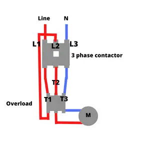
Yes, you can use a three-phase contactor to control a single-phase load by connecting the power terminals through the outer two poles of the contactor L1 and L3. Connect L3 to the load through the overload terminal T3.
Then reconnect the third middle pole of the contactor L2 from the overload first leg T1. Connect the motor to the overload T2. In this way, the motor current will pass through the three legs of the overload. Below is a simple wiring diagram.
Install my Free Android App on Google Play:
Electrical Cables Most Common Tables
And, my Electrical Calculations App “”
Discover more great content by subscribing to My channel
Looking to stay ahead of the game in the world of electrical engineering? Subscribe to my YouTube channel and gain access to exclusive content you won’t find anywhere else!
The staff I recommend
(Amazon Affiliate Links to products I believe are high quality):
- Economy 120 Volt/60Hz AC Power Source – Step-Down Voltage & Frequency Converters 1800W
- UNI-T Digital Multimeter Tester UT139C
- 50-Amp Extension Cord for RV “100ft”
- Voltage Stabilizer 110/220v
- Hair Dryer “best selling“
- TOSHIBA EM131A5C-BS Countertop Microwave Ovens
Disclaimer: This contains affiliate links to Amazon products. I may earn a commission for purchases made through these links.

