A current transformer (CT) is a type of electrical instrument transformer used to measure or monitor alternating current (AC) in electrical circuits. It works by transforming a high primary current into a lower, proportional secondary current, which is suitable for measurement or protection devices.
CTs are commonly used in various applications, including electricity metering, power quality monitoring, and protective relaying in electrical systems.
They provide electrical isolation between the primary circuit (where the current flows) and the secondary circuit (where measurements are taken), ensuring safety and accuracy in current measurement and control.
Table of Contents
What happens to the voltage in a current transformer?
In a current transformer (CT), the voltage across its secondary winding is typically proportional to the current flowing through its primary winding.
The primary winding of a current transformer is connected in series with the circuit carrying the current you want to measure, and the secondary winding is connected to a measuring or protection device. Here’s what happens to the voltage in a current transformer:
- Voltage Transformation: The primary winding of the CT is designed to have very few turns of wire compared to the secondary winding. This design allows for a significant reduction in the voltage on the secondary side compared to the voltage on the primary side. The turns ratio, which is the ratio of the number of turns in the primary winding to the number of turns in the secondary winding, determines this voltage transformation.
- Proportional Voltage: The voltage across the secondary winding of the CT is directly proportional to the current flowing through the primary winding. This is in accordance with the principle of electromagnetic induction, as described by Faraday’s law. The voltage is proportional in magnitude and phase to the current, and the ratio between the primary and secondary currents is equal to the turns ratio.
- Step-Down Voltage: In most cases, CTs are designed as step-down transformers, meaning that the voltage on the secondary side is lower than the voltage on the primary side. For example, if you have a CT with a turns ratio of 1000:1, and 1000 amperes of current flow through the primary winding, you would expect to get 1 ampere on the secondary winding. The voltage on the secondary side would be much lower than the voltage on the primary side.
- Isolation: CTs provide electrical isolation between the primary circuit and the secondary circuit. This isolation ensures that the measuring or protection devices connected to the secondary winding are safe from the high voltages present in the primary circuit.
What Is The Current Transformer Burden?
The current transformer (CT) burden refers to the impedance or load connected to the secondary winding of the CT. It is essentially the combination of resistance and reactance (inductive or capacitive) presented to the secondary winding by the external circuitry, including the measuring or protective devices connected to the CT.
The burden is important to consider because it affects the accuracy and performance of the CT in terms of its current measurement capabilities. The burden has the following key components:
- Resistance (R): This represents the actual resistance in the external circuit connected to the secondary winding of the CT. It’s usually measured in ohms (Ω) and is typically associated with the resistance of the wires, connections, and any external resistors or components in the circuit.
- Reactance (X): The reactance represents the inductive or capacitive impedance introduced by the connected devices or the wiring. Inductive reactance (XL) is associated with inductors, while capacitive reactance (XC) is associated with capacitors. Reactance is typically measured in ohms (Ω) and is frequency-dependent.
The total burden (Z) is the combination of resistance and reactance:
[Z = R + jX]
Where:
- (Z) is the total burden in ohms (Ω).
- (R) is the resistance in ohms (Ω).
- (jX) is the reactance in ohms (Ω) and is represented as a complex number because it can be inductive ((j) positive) or capacitive ((j) negative) in nature.
It’s important to ensure that the CT burden does not exceed the rated burden of the CT. The rated burden is a specification provided by the CT manufacturer and represents the maximum external impedance that the CT can tolerate while still providing accurate current measurements. Exceeding the rated burden can lead to inaccurate readings and may even damage the CT.
When designing or using CTs in electrical systems, it’s essential to calculate and consider the total burden to ensure the CT operates within its specified accuracy limits. This involves taking into account the resistance and reactance of the external circuitry and making sure they do not exceed the CT’s rated burden.
Current Transformer Burden Calculation, Formula, And Example?
The burden of a current transformer (CT) represents the impedance or load connected to the secondary winding of the CT. It includes both resistance (R) and reactance (X) components. To calculate the burden, you can use the following formula:
[Z = R + jX]
Where:
- (Z) is the total burden in ohms (Ω).
- (R) is the resistance in ohms (Ω).
- (X) is the reactance in ohms (Ω), represented as a complex number (with (j) for the imaginary unit), accounting for inductive or capacitive effects.
Here’s how you can calculate the burden:
- Determine the total resistance ((R)) in the secondary circuit. This includes the resistance of the wires, connections, and any external resistors or components connected to the CT.
- Determine the total reactance ((X)) in the secondary circuit. Reactance can be inductive (positive (jX)) or capacitive (negative (jX)) and depends on the components and the frequency of the AC current being measured.
- Add the resistance and reactance components to get the total burden ((Z)).
Example:
Let’s say you have a CT with the following specifications:
- Rated primary current (I_p): 1000 A
- Rated secondary current (I_s): 5 A
- Rated burden: 10 VA
Assuming the secondary current is 5 A, you want to calculate the burden on the CT’s secondary side. You can use the formula:
[Z = R + jX]
Assume the resistance (R) of the secondary circuit is 2 ohms, and the reactance (X) due to inductance is 5 ohms (j5Ω) at the operating frequency.
[Z = 2 + j5]
Now, you have the total burden as a complex impedance, 2 + j5 ohms.
Ensure that this total burden does not exceed the rated burden of the CT (in this case, 10 VA). If the total burden is within the CT’s rated burden, it will operate accurately and safely. If the burden exceeds the rated value, you may need to adjust the external circuitry, reduce the impedance, or consider a CT with a higher-rated burden.
In practice, CT burden calculations should be performed to ensure the CT operates within its specified accuracy limits and does not overload or damage the CT when connected to the secondary circuit.
The actual impedance values will depend on the specific circuit and the characteristics of the components connected to the CT.
Current Transformer Ratio Meaning And Formula
The current transformer (CT) ratio, often referred to as the transformation ratio, is a crucial parameter that defines the relationship between the primary current and the secondary current in a CT.
It tells you how many times the primary current is reduced or transformed to obtain the secondary current. The CT ratio is typically expressed in the form of a ratio, such as “N:1” or “N/1,” where “N” represents the transformation ratio.
The formula for the current transformer ratio is as follows:
CT Ratio (N)=Ip/Is
Where:
- (N) is the CT ratio.
- (Ip) is the primary current, the current flowing through the primary winding of the CT.
- (Is) is the secondary current, the current produced on the secondary winding of the CT.
In this formula, you divide the primary current by the secondary current to determine the CT ratio. It indicates how many times the primary current is reduced to obtain the secondary current. The CT ratio is a critical factor in ensuring that the secondary current is suitable for measurement or protection devices.
Here are a few key points about CT ratios:
- Step-Down Transformer: CTs are typically designed as step-down transformers, meaning that the secondary current is lower than the primary current. Therefore, the CT ratio is usually greater than 1.
- Accuracy: The CT ratio is an essential parameter for the accuracy of current measurements. It ensures that the secondary current is proportional to the primary current, and errors are minimized.
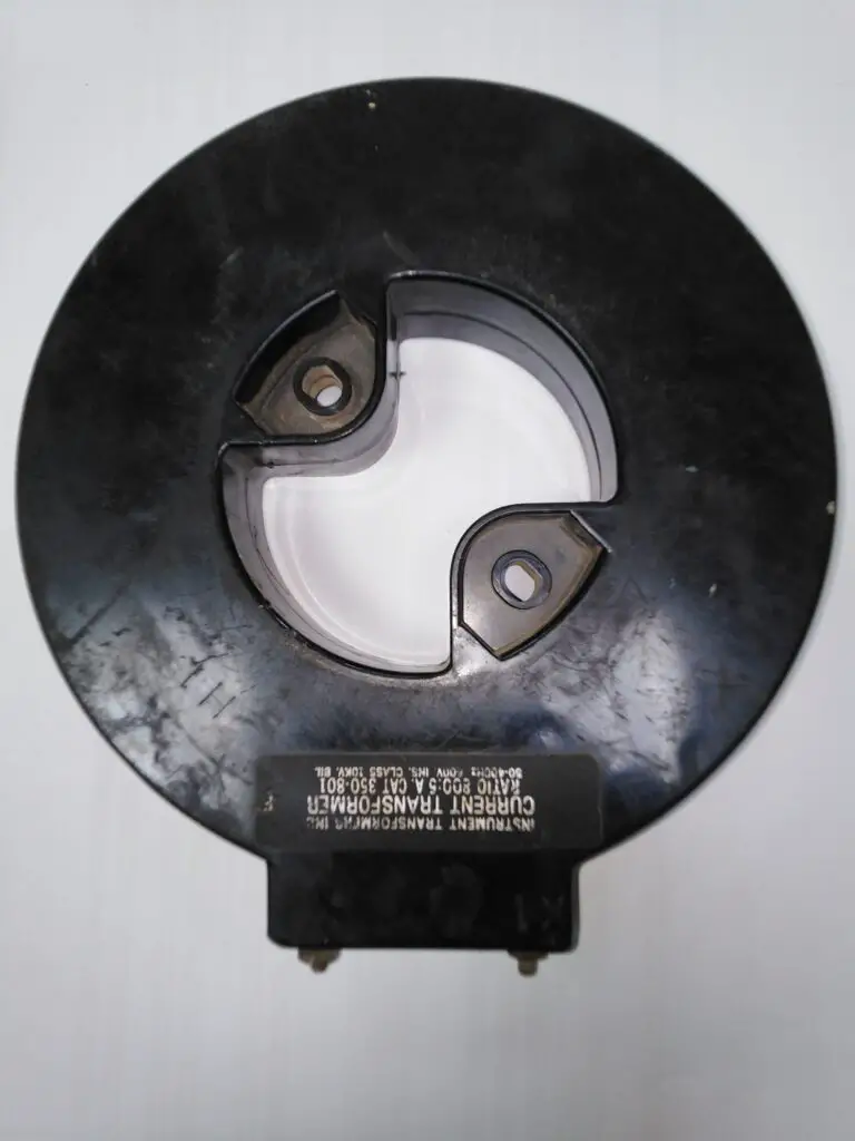
- Rating: CTs are often labeled with their rated primary and secondary current values, as well as the CT ratio. For example, a CT might be labeled as “1000/5A,” which means it has a 1000:5 CT ratio, and it’s designed to provide 5 amperes on the secondary winding when 1000 amperes flow through the primary winding.
- Protection and Metering: CTs are used in various applications, including protective relaying, metering, and control. The CT ratio must match the requirements of the specific application.
How To Select Current Transformer Ratio?
Selecting the appropriate current transformer (CT) ratio is crucial to ensure accurate and reliable current measurements in electrical circuits.
The CT ratio should be chosen based on the specific requirements of your application. Here are the steps to help you select the right CT ratio:
- Determine the Primary Current (Ip): First, you need to know the range of the primary current that the CT will be monitoring. This is the current flowing through the conductor you want to measure. You should consider both the normal operating current and any potential fault currents if you are using the CT for protection purposes.
- Identify the Required Secondary Current (Is): Determine the desired secondary current that will be compatible with the measuring or protection devices you plan to connect to the CT. In many cases, this will be a standard current value such as 1A or 5A on the secondary side.
- Calculate the CT Ratio (N): Use the formula for CT ratio: [ N = Ip/Is ] Plug in the primary current (Ip) and desired secondary current (Is) to calculate the CT ratio (N).
- Select the CT Ratio: Based on the calculated CT ratio, choose a CT with a ratio that is equal to or close to the calculated value. CTs with standard ratios like 100:5, 200:5, 400:5, etc., are readily available. Choose the ratio that is the closest match to your calculated value.
- Consider the Accuracy Class: CTs come in different accuracy classes, such as Class 0.2, Class 0.5, Class 1, and Class 5, among others. The accuracy class determines how closely the CT’s secondary current matches the primary current. For precise measurements, choose a CT with a higher accuracy class.
- Ensure the CT Burden Matches the Load: The CT burden is the total impedance (resistance and reactance) connected to the secondary winding. Ensure that the burden (external circuitry) connected to the CT does not exceed the CT’s rated burden. Exceeding the rated burden can affect accuracy. If needed, calculate the total burden and make sure it’s within limits.
- Consider Safety and Installation Requirements: Ensure that the physical size and connection method of the CT is suitable for your installation. Also, consider any safety requirements or electrical codes that apply to your application.
- Consult Manufacturer Specifications: Always refer to the manufacturer’s specifications and datasheets for the CT you plan to use. These documents provide detailed information about the CT’s performance characteristics, accuracy, and rated burden.
- Calibration and Testing: After selecting a CT, it’s important to calibrate and test it in the actual application to ensure it meets the required accuracy and performance criteria.
Keep in mind that selecting the right CT ratio is critical for accurate current measurement and protection, and it should be based on the specific requirements of your electrical system or application.
What Causes A Current Transformer To Burn?
Several factors can contribute to the burning or overheating of a current transformer (CT). Here are some common causes:
- Overloading:
- Exceeding the rated current of a CT can lead to overheating. Current transformers are designed to handle a specific range of currents, and exceeding this range can cause excessive heat buildup, leading to insulation failure and ultimately resulting in burning.
- Saturation:
- Saturation occurs when the magnetic core of the CT cannot handle the magnetic flux generated by the primary current. This can happen when the primary current is too high or if there is a fault condition. Saturation can lead to distorted secondary currents, inaccurate measurements, and increased heating.
- Short Circuits:
- Short circuits in the secondary circuit or across the burden can lead to excessive currents flowing through the CT. This can cause overheating and damage to the windings and insulation.
- Incorrect Connection:
- Incorrectly connecting a CT, such as reversing the primary and secondary connections, can disrupt the normal flow of current through the transformer. This can lead to inaccurate measurements, saturation, and overheating.
- Voltage Surges:
- Voltage surges, whether caused by lightning or other transient events, can induce high voltages in the secondary winding of the CT. If these voltages exceed the insulation capability of the CT, it can result in insulation breakdown and burning.
- Poor Quality or Faulty CTs:
- CTs that are of poor quality or have manufacturing defects may be more prone to overheating. Faulty insulation, inadequate design, or substandard materials can contribute to the failure of a CT.
- Environmental Factors:
- Harsh environmental conditions, such as extreme temperatures, humidity, or exposure to corrosive substances, can affect the performance of a CT and contribute to its degradation and eventual burning.
- Aging and Wear:
- Over time, the insulation of a CT may degrade due to factors like aging, wear, or exposure to environmental conditions. This can reduce the CT’s ability to withstand heat and lead to burning.
- Incorrect Burden:
- Connecting an incorrect burden (load) to the secondary of the CT can result in excessive current flow and overheating. The burden should match the specifications provided by the CT manufacturer.
To prevent burning and ensure the proper functioning of current transformers, it’s crucial to adhere to the manufacturer’s guidelines, use the CT within its specified ratings, and regularly inspect and maintain the equipment.
If there are concerns about the performance of a CT, it should be tested, and if necessary, replaced or repaired by qualified personnel.
Read also my articles: Transformer burnout, causes and solutions for more information about what can cause an ordinary transformer to burn.
electrical4uonline
What Happens When Current Transformer Secondary Opens On Live?
If a current transformer (CT) secondary circuit opens while the primary circuit is energized, it can lead to a potentially hazardous situation. Here are some of the consequences and considerations:
- Dangerous Voltage Spikes:
- When the CT secondary circuit opens, it interrupts the flow of current. This sudden interruption can lead to a rapid collapse of the magnetic field within the CT, resulting in a voltage spike on the secondary side. The magnitude of this voltage can be much higher than the normal secondary voltage and pose a danger to connected equipment and personnel.
- Insulation Stress:
- The sudden voltage spike caused by the open secondary can stress the insulation of the CT. If the insulation is not designed to handle such voltage levels, it may break down, leading to a short circuit or other electrical failures.
- Safety Hazards:
- The elevated voltage levels can pose a safety hazard to personnel working in the vicinity of the CT. There is a risk of electric shock or injury if appropriate precautions are not taken.
- Equipment Damage:
- The high voltage generated during the open secondary condition can damage connected equipment, such as meters, relays, or other devices connected to the CT secondary. It may cause insulation breakdown, component failure, or even permanent damage to the equipment.
- Inaccurate Measurements:
- With the secondary circuit open, the CT is no longer able to provide accurate current measurements. This can impact the operation of protective relays and other devices relying on the CT for current information.
- Loss of Protective Function:
- Current transformers are often used in protective relay schemes to detect abnormal currents and initiate protective actions. If the secondary circuit is open, the protective relay may not receive the correct current information, potentially leading to a failure of the protective system to operate as intended.
- System Instability:
- The sudden loss of current flow in the secondary circuit can affect the stability of the electrical system. Protective devices may not function correctly, and the system may be vulnerable to faults or abnormal conditions.
To prevent these issues, it’s crucial to follow proper safety procedures when working with current transformers, including ensuring that the secondary circuit is properly connected and not left open while the primary circuit is energized.
Additionally, regular maintenance and testing of current transformers can help identify and address potential issues before they become critical.
If a current transformer is suspected to be faulty or has an open secondary, it should be inspected and repaired or replaced by qualified personnel.
Is the Current Transformer A Step Up Or A Step-Down?
High currents exist on power lines and within high-power circuits. It is often difficult to measure these currents directly.
Current transformers are used to reduce the line current to make it easier to determine. The current Transformer is usually a step-down transformer. It will lower the current level to that level measured with an ammeter.
As we all know, ammeters can measure a range of current that can be approximately 500 to 750 A. However, the current levels of AC circuits are high enough that they can’t be measured with an ammeter. Thus, the CT is installed in series, with the primary winding connected to the circuit and the secondary winding attached to a current measurement instrument.
The power of the transformer is the same for both the primary side and the secondary side. The only way to reduce the current is to step up the voltage.
For more information about Step Up and Step Down Transformers, read my detailed article here.
current transformers vs. ordinary power transformers?
Current transformers (CTs) and power transformers serve different purposes in an electrical system, and they have distinct designs and characteristics tailored to their specific functions. Here are the key differences between current transformers and ordinary power transformers:
- Primary Function:
- Current Transformers (CTs): The primary function of a current transformer is to measure or monitor the current flowing in a conductor. CTs are used to step down high currents to a standardized, lower current suitable for measurement and protection devices.
- Power Transformers: The primary function of a power transformer is to transfer electrical energy between two or more circuits. Power transformers step up or step down voltage levels, allowing efficient transmission and distribution of electrical power.
- Winding Configuration:
- Current Transformers (CTs): CTs have a primary winding (connected in series with the current to be measured) and a secondary winding (connected to measuring or protective devices). The turns ratio of the windings determines the current transformation ratio.
- Power Transformers: Power transformers have primary and secondary windings as well, but their primary purpose is to transform voltage. The turns ratio in power transformers determines the voltage transformation ratio.
- Turns Ratio:
- Current Transformers (CTs): The turns ratio of a CT is designed to transform high currents to a standard secondary current, typically 5A or 1A. The turns ratio is crucial for accurate current measurement.
- Power Transformers: The turns ratio of a power transformer determines the voltage transformation between the primary and secondary sides. It is crucial for voltage conversion in power transmission and distribution.
- Accuracy and Burden:
- Current Transformers (CTs): CTs are designed for high accuracy in current measurement. They have a burden, which is the impedance connected across the secondary winding, and the accuracy can be affected if the burden is not within specified limits.
- Power Transformers: While power transformers need to be efficient in energy transfer, their accuracy requirements are not as stringent as those of current transformers. Power transformers are designed to minimize losses and maximize efficiency.
- Core Saturation:
- Current Transformers (CTs): CTs are designed to operate in the linear region of their magnetization curve to avoid saturation. Saturation can lead to inaccurate current measurements.
- Power Transformers: Power transformers may experience some degree of saturation, but it is managed within acceptable limits. Saturation in power transformers is not as critical as in current transformers.
- Connection to Loads:
- Current Transformers (CTs): CTs are typically connected to measuring devices, protective relays, or meters to provide accurate current information.
- Power Transformers: Power transformers are connected to loads or other transformers to transfer electrical power between different voltage levels in a power system.
In summary, current transformers are specialized transformers designed for accurate current measurement and protection applications, while ordinary power transformers are designed for the efficient transfer of electrical power between different voltage levels in a power system.
How Does Current Transformer Work In DC Circuit?
As a general rule, CTs are used to measure AC currents in AC circuits. The CT is technically sensitive to DC as well. When we use it with dc circuits, the core will become saturated quickly, and the indication will stop working.
The issue with this method of sensing DC current is that the CT’s windings eventually get saturated when the current flows in just one direction, making it impossible for the CT to continue taking precise measurements.
Hall effect sensors with a gap in the core for the sensor are frequently used for DC, but when used in permanent installations, they frequently exhibit sensitivity drift.
The usage of orthogonal fluxgates, which employ two orthogonal coils, one of which alternatively enters saturation, is another choice for a permanent installation.
It is the second coil from which the DC current is measured. To find an AC component, if it’s there, a Rogowski coil is inserted.
What is the creepage distance of the current transformer?
Whether it be a current transformer or another electrical device, the creepage distance is the distance traveled over the insulator’s surface in the least amount of time.
The machine’s live components must be kept apart from the ground and the operator. By ensuring a safe distance between the live portion and the ground, this is accomplished.
The tank in a current transformer must be kept separate from the secondary box and the CT’s base. This is accomplished with the porcelain insulator’s assistance.
If a 420 kV Current Transformer is being insulated, then the distance between the CT tank and base needs to be extended in order for it to withstand a 1250 kVp lightning impulse.
Due to construction and economic constraints, we cannot expand the CT height over a certain point; therefore, we have instead increased the distance along the porcelain’s surface to safeguard the CT against surge and flashover. In a typical situation, the Creepage distance for 420 kV CT is 10500mm.
How A Current Transformer Is Connected With The Load?
There are two windings of a current transformer: the primary winding is connected to the load in series, which carries the actual current flowing to the load, while the secondary winding of the transformer is connected to a measuring device or a relay on the secondary winding of the transformer.
The measuring, sensing, and protection equipment are attached to the transformer’s secondary, which receives an alternating current as its primary.
The current-carrying conductor is the sole turn made by the primary of a CT, which normally has just one window. Its main never has more than a very small number of turns.
Depending on the size of the current that has to be stepped down, the secondary of the transformer has a number of turns.
The measuring equipment can be attached to the ends of the secondary coil, which is twisted around a laminated core made of ferromagnetic material.
Is Polarity Important When Connecting To Current Transformers?
Yes, Correct polarity must be observed when installing current transformers and connecting them to power metering and protection relays.
A CT’s polarity may occasionally be represented by an arrow; in this case, the arrow should point in the direction of the current flow when the CT is placed.
The polarity of a current transformer is defined by the clockwise or counterclockwise direction in which the coils are twisted around the CT’s core and by the direction in which the secondary leads are brought out of the transformer casing.
With the following designations to help with appropriate installation, all current transformers are subtractive polarity devices:
H1 = Primary current, the direction of the line
H2 = Primary current, forward-facing load
X1 = Secondary current
The H1 main lead and the X1 secondary lead are located on the same side of subtractive polarity transformers.
When a CT’s polarity is represented by an arrow, the arrow shall point in the direction of the current flow when the CT is placed.
Can I Connect the Current Transformer In the Reverse Direction?
No, you should not connect a current transformer (CT) in the reverse direction. Current transformers are designed to have a specific primary and secondary winding orientation, and connecting them in reverse can lead to inaccurate measurements and potentially damage the CT or connected equipment. Here’s why:
- Directionality:
- Current transformers have a specific directionality, with a designated primary side and a secondary side. The primary side is where the current to be measured flows, and the secondary side is where the reduced current is measured and sent to instruments. Reversing this direction disrupts the intended operation of the CT.
- Accuracy Issues:
- Connecting a CT in reverse can result in inaccurate measurements. The CT’s turn ratio, which defines the relationship between the primary and secondary currents, is designed with a specific winding arrangement. Reversing the CT would alter this ratio, leading to incorrect readings on the secondary side.
- Saturation and Core Damage:
- Current transformers are designed to operate within a specific range of current levels. Reversing the CT may cause it to operate outside its intended range, leading to saturation of the core. Saturation can result in distorted waveforms and inaccurate measurements. Additionally, prolonged saturation can damage the CT’s core.
- Safety Concerns:
- Incorrectly connecting a CT can lead to safety hazards. The CT is often used in conjunction with protective relays and devices. Reversing the CT could lead to improper operation of protective systems, potentially compromising the safety of the electrical system.
- Equipment Damage:
- In addition to inaccurate measurements, reversing a CT may lead to damage to the CT itself, as well as connected equipment. The CT is designed to operate under specific conditions, and reversing it can subject the device to conditions it is not designed for.
To ensure proper operation and accurate measurements, always follow the manufacturer’s instructions and guidelines when installing current transformers.
The correct orientation of the primary and secondary windings is crucial for the CT to function as intended and to provide reliable and safe measurements.
Why Is The Secondary Of the Current Transformer Grounded?
The secondary of a current transformer (CT) is grounded for safety and operational reasons. Here are a few key reasons for grounding the secondary of a current transformer:
- Safety of Personnel:
- Grounding the secondary circuit helps to prevent the buildup of high voltages relative to the ground. In the absence of grounding, the secondary circuit could float at a potential significantly different from the ground potential, which could pose a safety hazard to personnel.
- Fault Protection:
- Grounding the secondary helps to provide a low-impedance path for fault currents. In the event of a fault or a short circuit in the secondary circuit, grounding allows the fault current to flow to the ground, facilitating the operation of protective devices such as fuses or circuit breakers. This helps in isolating the fault and protecting the connected equipment.
- Accuracy of Measurement:
- Grounding the secondary minimizes the risk of external influences affecting the accuracy of current measurements. The grounded secondary helps to maintain a stable reference potential, reducing the impact of external electromagnetic interference.
- Avoiding Floating Potential:
- Without grounding, the secondary winding could float at a potential that is significantly different from ground. This floating potential could lead to unpredictable and potentially hazardous conditions in the system.
- Common Reference Point:
- Grounding provides a common reference point for the entire electrical system. This helps in maintaining consistency and coordination among various devices and components within the system.
It’s important to note that the grounding of a current transformer’s secondary is typically done at one point, often referred to as the grounding point or terminal. This grounding point is usually connected to the system ground or earth ground.
In summary, grounding the secondary of a current transformer is a crucial safety measure that ensures the accuracy of measurements, protects personnel and equipment during faults, and provides a stable reference potential for the overall electrical system.
For more about Electrical Grounding Read My Article Here.
Does A Current Transformer Has Oil?
The presence of oil in a current transformer (CT) depends on the specific design of the transformer.
Current transformers are generally categorized into two main types: dry-type (air-core) and oil-filled transformers.
- Dry-Type Current Transformers:
- Dry-type CTs do not use oil as an insulating or cooling medium. Instead, they rely on air or solid insulation materials. Dry-type CTs are often preferred in indoor applications, where the use of oil may be impractical or present safety concerns.
- Oil-Filled Current Transformers:
- Some current transformers are designed to be oil-filled. In these transformers, mineral oil or other insulating oils are used as both an insulating material and a cooling medium. Oil-filled current transformers are commonly used in outdoor applications or in environments where additional insulation and cooling are necessary.
The choice between dry-type and oil-filled CTs depends on factors such as the application, environmental conditions, and safety considerations.
Oil-filled CTs are generally more common in high-voltage and outdoor installations where the additional insulation and cooling properties of oil are beneficial.
It’s important to note that oil-filled transformers require proper maintenance to ensure the integrity of the insulation and cooling properties of the oil.
Periodic testing, monitoring, and, if necessary, oil replacement are part of the maintenance practices for oil-filled transformers.
Before working with or maintaining a current transformer, it’s essential to refer to the manufacturer’s documentation and guidelines to understand the specific design and requirements of the transformer in question. This information will help ensure the safe and proper operation of the current transformer.