
A transformer is an electrical static machine, that steps AC voltage up or down, and transfers AC power from one circuit to another with fixed power and frequency.
You may ask, Why do we consider the transformer a machine when it has no moving parts? The answer is that the rules of electric machines and transformers are the same. The transformer is a static machine.
While I was searching the transformer topics I found a question saying, Does a transformer have moving parts? No, transformers have no moving parts.
They are static machines that transfer electricity from one side to another with no moving parts. The only moving thing inside transformers is cooling oil.
Table of Contents
Transformer principle of operation
An electric transformer is a device that transfers electrical energy between two or more circuits through electromagnetic induction.
It operates based on the principle of electromagnetic induction, which was first discovered by Michael Faraday in the 19th century.
The basic components of a transformer include two coils of wire, known as the primary coil and the secondary coil, and a core made of a magnetic material.
The core is usually constructed of laminated iron or steel to enhance its magnetic properties and reduce energy losses.
Here’s a step-by-step explanation of the principle of operation of an electric transformer:
- Faraday’s Law of Electromagnetic Induction:
- When there is a change in magnetic flux through a coil of wire, an electromotive force (EMF) is induced in the coil. The magnitude of the induced EMF is proportional to the rate of change of magnetic flux.
- Primary Coil (Input Coil):
- The alternating current (AC) from the power source is applied to the primary coil. As the AC flows through the primary coil, it produces a changing magnetic field around it.
- Magnetic Field Induces Voltage in the Secondary Coil:
- The changing magnetic field in the primary coil induces a voltage in the secondary coil through electromagnetic induction. The voltage induced in the secondary coil is proportional to the rate of change of magnetic flux and the number of turns in the coil.
- Step-Up or Step-Down Transformation:
- The ratio of the number of turns in the primary coil to the number of turns in the secondary coil determines whether the transformer is a step-up or step-down transformer.
- If the primary coil has fewer turns than the secondary coil, it’s a step-up transformer, increasing the voltage.
- If the primary coil has more turns than the secondary coil, it’s a step-down transformer, decreasing the voltage.
- The ratio of the number of turns in the primary coil to the number of turns in the secondary coil determines whether the transformer is a step-up or step-down transformer.
- Energy Transfer:
- The induced voltage in the secondary coil can be used to power electrical devices or systems connected to the secondary circuit. Energy is transferred from the primary circuit to the secondary circuit without a direct electrical connection, making transformers essential for efficient power distribution.
- Conservation of Energy:
- The power in the primary coil is approximately equal to the power in the secondary coil, taking into account losses due to resistance and other factors.
In summary, the electric transformer operates on the principle of electromagnetic induction, allowing for the efficient transfer of electrical energy between circuits with different voltage levels.
Transformers play a crucial role in power transmission and distribution systems, allowing electricity to be generated at one voltage and then transformed to higher or lower voltages for efficient distribution and utilization.
Transformer parts?
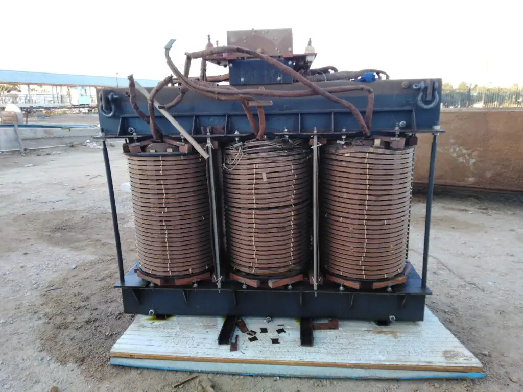
A typical transformer consists of several key parts, each serving a specific purpose in the device. Here are the main components of a transformer:
- Core:
- The core is a magnetic structure that provides a path for the magnetic flux generated by the current flowing in the windings. It is typically made of laminated iron or steel to enhance magnetic properties and reduce eddy current losses.
- Primary Coil:
- The primary coil, also known as the input coil, is where the electrical energy from the source is applied. The alternating current in the primary coil generates a changing magnetic field in the core.
- Secondary Coil:
- The secondary coil, also known as the output coil, is where the induced voltage is collected. The changing magnetic field in the core induces an electromotive force (EMF) in the secondary coil, allowing electrical energy to be transferred to the load.
- Windings:
- The primary and secondary coils consist of multiple turns of insulated wire wound around the core. The number of turns in each coil determines the voltage ratio between the primary and secondary sides.
- Insulation:
- Insulating materials are used to separate the windings and prevent electrical contact between them. This insulation is crucial to maintaining the integrity and safety of the transformer.
- Tank:
- Transformers are often housed in a tank filled with oil to dissipate heat generated during operation. The oil also provides insulation and helps cool the transformer.
- Bushing:
- Bushings are insulating devices that allow the connection of external conductors to the internal windings. They provide a means for electrical connections without compromising the insulation. Read my comprehensive article on Electric Transformer Bushings.
- Tap Changer:
- Some transformers have a tap changer that allows the adjustment of the turns ratio, enabling the regulation of output voltage. This is particularly useful for compensating for variations in the input voltage or load.
- Cooling System:
- Large transformers often have cooling systems to dissipate heat generated during operation. This can include natural convection cooling, forced air cooling, or liquid cooling systems, depending on the transformer’s size and application.
- Breather:
- A breather is a device attached to the transformer tank that helps prevent moisture from entering the transformer. It typically contains a desiccant to absorb moisture from the air.
- Conservator:
- A conservator is a tank or reservoir connected to the transformer that allows for the expansion and contraction of the transformer oil as it heats and cools. It helps maintain the oil level and prevents contact with air.
These components work together to facilitate the efficient transfer of electrical energy from the primary to the secondary circuit while minimizing energy losses and ensuring the safety and reliability of the transformer.
The specific design and features of a transformer may vary depending on its application and intended use.
Install my Free Android App on Google Play:
Electrical Cables Most Common Tables
And, my Electrical Calculations App “”
Discover more great content by subscribing to My channel
Looking to stay ahead of the game in the world of electrical engineering? Subscribe to my YouTube channel and gain access to exclusive content you won’t find anywhere else!
The staff I recommend
(Amazon Affiliate Links to products I believe are high quality):
- Economy 120 Volt/60Hz AC Power Source – Step-Down Voltage & Frequency Converters 1800W
- UNI-T Digital Multimeter Tester UT139C
- 50-Amp Extension Cord for RV “100ft”
- Voltage Stabilizer 110/220v
- Hair Dryer “best selling“
- TOSHIBA EM131A5C-BS Countertop Microwave Ovens
Disclaimer: This contains affiliate links to Amazon products. I may earn a commission for purchases made through these links.
