
Table of Contents
What is an electrical grounding system?
An electrical grounding system, or earthing system, is the process of connecting all metallic parts of electrical devices to the ground through an electrical low-resistance path, to provide safety for humans and devices.
Connecting electrical equipment to the grounding provides an alternative path for fault current.
The fact that electric current flows through the lower resistance path makes grounding electrical equipment a safety matter, in case of an electrical fault, the current will go through the grounding cable rather than going into a human body touching the faulty equipment.
For more information about Home and Workplace Electrical Safety, Read my article on my SAFETYFRENZY site.
Working principle of electrical grounding
Grounding system provides a low resistance path for static charges and electrical current in fault condition to earth.
In the case of electrical faults, currents take the lowest resistance path. By grounding the device, we give electricity an alternative path instead of the human body.
As we know electrons follow through the shortest possible path in the circuit. If any fault comes into the electrical wiring, the electrical grounding will provide the shortest path to your electrical system And a large amount of electrical current will flow into the ground.
For this process, we connect a copper conductor with a metal rod in the wiring system. Now these are further connected with panels and are placed deep into the ground.
Whenever a fault occurs in an electrical system, the grounding system provides the shortest possible path to the current.
Earthing resistance should be less than or equal to 5 Ohms to be effective. The value of the earthing resistance depends on some factors like soil resistivity, humidity, number of earthing rods, and cable size.
Why is electrical grounding important?
- Electrical grounding plays an important role in the safety of electrical wiring systems.
- Ground has low resistance, Proper electrical grounding provides the shortest path to excessive current and hence protects devices or even the whole electrical system from damage.
- lake of good grounding is dangerous and may lead to equipment failure and human injuries.
Grounding system inspection
Over time, ground rods are degraded due to soil moisture, salt, and temperature. This means that the grounding resistance becomes larger than 5 Ohms and the system is not effective for its purpose.
For all the above it’s important to make periodic maintenance and check the system of earthing.
To do so measure grounding resistance and record its value every three years and visually check and inspect grounding cables and connections for any corrosion and damage.
How to measure grounding resistance?
It’s an easy job to measure the resistance value of a grounding system using a clamp meter like Fluke 1630-2 FC Earth Ground Clamp, it needs no special training to use it.
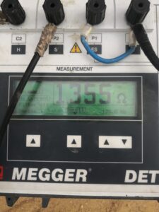
The Megger earthing meter is another way to measure grounding resistance. The device has three cables, one to connect with the earthing rod and two others connected to testing rods, 50cm copper rods.
We dig the testing rods to about 40cm depth, connect them with the device, and connect the other cable to the earthing rod to measure its resistance. Turn on the device and you’re done.
What devices need a grounding system?
All metallic parts of electrical equipment such as electrical transformers, motors, and generators should be grounded through low resistance cable to the earthing system.
In case of the insulation of electrical equipment fails for any reason the voltages which may present on the metallic body of the equipment should find some path to be discharged.
If the equipment is not grounded, these dangerous voltages may transferred to anyone who touches the equipment resulting in dangerous electric shock.
Should I ground my house?
To protect your family against electrical shock you should connect an electrical grounding cable to your house and make a proper earthing system for it.
Refrigerators, water electrical heaters, and washers in most cases have a metallic body which mean they can cause an electric shock if the insulation of electrical parts degrades.
Connecting these home appliances to a good grounding system can save your and your family members’ lives.
How much should a grounding resistance be?
Typically, for electrical substations and industrial facilities, grounding resistance values are often specified in the range of 1 ohm to 5 ohms or lower, depending on local regulations and the specific application. Residential and commercial buildings may have less stringent requirements, but it still varies by location and circumstances.
The acceptable grounding resistance value depends on various factors, including the specific electrical system, safety requirements, and local regulations. Grounding resistance is a measure of how effectively the grounding system dissipates electrical fault currents into the ground.
In general, lower grounding resistance values are better because they indicate a more efficient grounding system. However, there are no universally fixed values for grounding resistance, as they can vary depending on the following factors:
- Electrical Code and Standards: Different countries and regions may have their own electrical codes and standards that specify maximum allowable grounding resistance values for various applications. These standards often provide guidance on what is considered safe and acceptable for specific installations.
- Electrical System Type: The type of electrical system and the level of fault current it can produce can influence grounding resistance requirements. High-voltage systems may have stricter requirements compared to low-voltage systems.
- Equipment and Facility Needs: The sensitivity of the equipment and the criticality of the facility’s operations can impact grounding requirements. For sensitive electronic equipment or facilities where electrical continuity is crucial, lower grounding resistance may be specified.
- Soil Conditions: The conductivity of the soil in which the grounding system is installed plays a significant role. Soil resistivity varies from one location to another and affects the overall grounding resistance. In areas with high soil resistivity, achieving low grounding resistance can be more challenging.
- Grounding System Design: The design of the grounding system, including the number and arrangement of ground rods, electrodes, and conductors, can influence the achievable grounding resistance.
To determine the appropriate grounding resistance for a particular installation, it is essential to consult local electrical codes and standards and consider the specific needs of the electrical system and facility.
Grounding systems are designed and tested to ensure electrical safety and a qualified electrician or engineer should be involved in their design and installation to ensure compliance with local regulations and safety standards.
How long the ground rod should be?
The length of a ground rod, often referred to as an “earth electrode,” depends on several factors, including the soil’s resistivity, the specific grounding requirements, and local electrical codes and standards. Ground rods are an essential part of an electrical grounding system, and their length is designed to ensure the effective dissipation of electrical fault currents into the earth.
In general, ground rods used in residential and commercial installations are typically 8 to 10 feet (2.4 to 3 meters) in length. However, there are cases where longer ground rods may be necessary, especially in areas with higher soil resistivity.
Here are some considerations for determining the appropriate length of a ground rod:
- Soil Resistivity: The resistivity of the soil plays a significant role in determining ground rod length. In areas with low soil resistivity (high conductivity), shorter ground rods may be sufficient. In contrast, in areas with high soil resistivity (low conductivity), longer ground rods may be necessary to achieve the desired grounding resistance.
- Electrical Code and Standards: Local electrical codes and standards often specify the minimum length of ground rods required for different applications. It’s essential to consult these regulations to ensure compliance.
- Grounding Requirements: The grounding requirements for the specific electrical system being installed can also influence ground rod length. For critical systems or those with high fault current levels, longer ground rods may be specified to achieve lower grounding resistance.
- Soil Conditions: It’s essential to assess the soil conditions at the installation site, including soil resistivity, moisture content, and composition, to determine the most appropriate ground rod length.
- Engineering Evaluation: In some cases, an engineering evaluation or soil resistivity test may be necessary to determine the optimal length of the ground rod for a particular installation.
- Multiple Rods: In situations where the soil resistivity is particularly high, it may be necessary to install multiple ground rods connected in parallel to achieve the desired grounding performance.
In summary, the length of a ground rod should be determined based on a combination of factors, including local regulations, soil conditions, electrical system requirements, and engineering evaluations.
It’s crucial to consult with a qualified electrician or engineer who can assess the specific needs of the installation and ensure that the grounding system is designed and installed in accordance with safety standards and local codes.
How Does Grounding Prevent An Electric Shock?
Grounding is an essential safety measure that helps prevent electric shocks by providing a safe path for electrical fault currents to flow into the ground, effectively grounding any potentially dangerous electrical energy. Here’s how grounding works to prevent electric shocks:
- Electrical Faults: In electrical systems, faults can occur due to various reasons, such as damaged wiring, equipment malfunction, or human error. When a fault occurs, it can create a path of low resistance for electricity to flow, potentially causing a hazardous situation.
- Grounding Conductor: A grounding system includes a grounding conductor, which is typically a wire or a metal conductor that is intentionally connected to the earth (ground). This conductor is used to establish a direct, low-resistance path to the ground.
- Connection to Ground: The grounding conductor is connected to a ground electrode, such as a ground rod or a grounding plate, which is buried in the earth. This connection ensures a reliable electrical connection to the ground.
- Electrical Equipment Grounding: In electrical systems, equipment, and appliances are equipped with grounding conductors and connections to ensure that any unintended electrical currents, such as those from a fault, have a safe path to the ground.
- Fault Current Path: When a fault occurs in an electrical circuit (e.g., a short circuit or ground fault), it creates an unintended path for electrical current to flow. In a properly grounded system, this fault current is directed into the grounding conductor and connected to the ground electrode.
- Safe Discharge: The earth itself is a good conductor of electricity. When fault current is directed into the ground through the grounding system, it dissipates harmlessly into the earth, away from people and equipment.
- Voltage Reduction: Grounding also helps reduce the voltage potential between conductive surfaces and the earth. This reduction in voltage potential minimizes the risk of electric shock by ensuring that the potential difference between a person or object and the earth remains low.
In summary, grounding prevents electric shocks by providing a safe path for fault currents to flow into the ground rather than through people, equipment, or other conductive surfaces.
It serves as a protective measure that redirects electrical energy away from potential sources of harm and reduces the risk of electrical accidents, such as shocks and fires.
Properly designed and maintained grounding systems are crucial for electrical safety in homes, buildings, and industrial facilities.
Can Any Wire Be Used As a Ground Wire?
In general, copper is often preferred for grounding conductors due to its excellent conductivity and corrosion resistance.
However, the specific material choice should align with the requirements of your electrical system and local regulations. Always consult with a qualified electrician or follow local electrical codes and standards when selecting grounding conductor materials.
Grounding conductors, or ground wires, are typically made from materials that are good conductors of electricity and resistant to corrosion. The most common materials used for grounding conductors are:
- Copper: Copper is one of the most widely used materials for grounding conductors due to its excellent electrical conductivity and corrosion resistance. It is highly effective in carrying fault currents and is often preferred for grounding applications.
- Aluminum: Aluminum is another material used for grounding conductors. It is less expensive than copper and still offers good electrical conductivity. However, aluminum conductors may require larger sizes than copper to achieve the same current-carrying capacity.
- Copper-Clad Steel (CCS): Copper-clad steel conductors consist of a steel core with a layer of copper bonded to the surface. These conductors combine the high strength of steel with the good conductivity of copper. They are often used in specific applications where a combination of strength and conductivity is required.
- Bare Wire: Grounding conductors are often left bare (without insulation) or with minimal insulation, such as green insulation. Bare wire ensures low-resistance fault current paths and is commonly used for grounding electrodes and connections.
The choice of grounding conductor material depends on factors such as:
- Electrical system requirements: The size and material of the grounding conductor should be chosen based on the fault current-carrying capacity of the system.
- Local electrical codes and standards: Electrical codes and standards in your area may specify the acceptable materials and sizes for grounding conductors.
- Cost considerations: Copper is an excellent conductor but can be more expensive than aluminum. The choice of material may be influenced by cost considerations, especially in large-scale installations.
- Environmental conditions: Consider the environmental conditions of the installation site. Copper is corrosion-resistant, making it suitable for most environments, while aluminum may require additional protection in corrosive environments.
For more information about electrical conductors, you can check out my detailed article.
Can You Ground with Aluminum Wire?
Yes, you can use aluminum wire for grounding purposes in electrical systems. Aluminum is a suitable material for grounding conductors, and it has been used in various applications for many years.
However, there are some important considerations and best practices to follow when using aluminum wire for grounding:
- Sizing: When using aluminum wire for grounding, it’s essential to ensure that the wire size (gauge) is adequate to handle the fault current expected in the electrical system. The sizing should conform to local electrical codes and standards, which typically specify the minimum size of grounding conductors based on the fault current-carrying capacity of the system.
- Terminations: Aluminum wire should be terminated using connectors and devices that are specifically rated for use with aluminum conductors. Aluminum wiring connections require connectors designed to accommodate the different thermal expansion characteristics of aluminum compared to copper. Properly rated connectors help prevent overheating and ensure secure, reliable connections.
- Anti-Oxidation Compounds: To mitigate the potential for oxidation and corrosion, which can reduce conductivity, an anti-oxidation compound may be applied to aluminum connections. This compound helps maintain electrical contact and prevents the formation of aluminum oxide.
- Torque Specifications: Proper torque values for tightening connections are crucial when working with aluminum wire. Over-torquing can damage the wire or connectors, while under-torquing can lead to loose connections, resistance, and overheating.
- Insulation and Protection: Grounding conductors are often left bare (uninsulated) or may have minimal insulation, such as green insulation. Proper protection should be provided to prevent physical damage to the conductor, especially in outdoor or exposed installations.
- Compliance with Codes: Always ensure that your use of aluminum wire for grounding is in compliance with local electrical codes and standards. Local codes may specify specific requirements for the use of aluminum conductors in grounding applications.
While aluminum is a suitable material for grounding conductors, it’s crucial to follow best practices, use appropriate connectors and terminations, and adhere to local regulations to ensure the safe and effective use of aluminum wire for grounding purposes.
Consulting with a qualified electrician or electrical engineer is recommended to ensure compliance with all applicable standards and safety guidelines.
Can I Touch Earth Wire?
Yes, you can touch the earth wire because earth wires do not carry any electric current and have exposed cables and connectors. It’s safe as long as there aren’t any electrical surges or faults.
An earth wire takes excessive electric current from electrical circuits when a surge or electrical problem is identified. The earthing wire conducts electricity to the earth via a grounding rod or pipe, where it may be safely neutralized.
It’s important to note that while the earth wire is generally safe to touch, it is not a substitute for proper electrical safety practices.
When working on electrical systems or installations, always follow safety guidelines, de-energize circuits when necessary, and use personal protective equipment as required.
If you are not trained or experienced in working with electrical systems, it is advisable to seek the assistance of a qualified electrician or technician to ensure your safety.