Fifteen years ago, during my employment at a factory, the electricity bill was unreasonably high due to the poor power factor of the factory loads. The electricity company charged for reactive power as well, motivating us to enhance the power factor.
In addressing this problem, we installed a capacitor bank in parallel with the factory’s main power source to enhance the power factor of the entire load. This solution proved effective in reducing costs.
Table of Contents
What is the Power Factor?
Power factor is the ratio of active power, measured in kilowatts, to apparent power, measured in kilo-volt amperes (or in kVA), power factor is the measure of effective use of electrical energy.
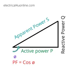
Below, is the power factor triangle, which shows the relation between power factor, active and reactive power.
Power factor triangle
Apparent power is the measure of the total amount of power that is used to run electrical equipment, active and reactive.
The power factor is how effectively you are using electrical energy. It is expressed as a number less than or equal to 1.
The lower the power factor, the less efficient electrical power usage. For well-designed electrical motors the PF = 0.95 while for single-phase bad motors pf = 0.75
Power factor formula
The power factor (PF) in an electrical system is calculated using the following formula:
Power Factor (PF)=cos(θ)
In this formula:
θ represents the phase angle between the voltage (V) and current (I) waveforms.
The power factor is the ratio of real power (P) to apparent power (S), and it is also expressed in terms of the angle θ:
Power Factor (PF)=Real Power (P) / Apparent Power (S)
Mathematically, the relationship between real power, apparent power, and power factor is given by:
Real Power (P)=Apparent Power (S)×Power Factor (PF)
This relationship can be rearranged to solve for apparent power or power factor as needed.
It’s important to note that the power factor is a dimensionless quantity ranging from 0 to 1. A power factor of 1 (or 100%) is referred to as a unity power factor, indicating perfect alignment between voltage and current waveforms.
A power factor less than 1 indicates a phase difference and the presence of reactive power in the system. Power factor correction measures, such as adding capacitors, are often employed to improve the power factor in situations where inductive loads cause a lagging power factor.
Power Factor Correction (PFC) is a technique used in electrical engineering to improve the power factor of a power supply.
The power factor is a measure of how effectively electrical power is being converted into useful work output. It is the ratio of real power (in kilowatts) to apparent power (in kilovolt-amperes) and is expressed as a number between 0 and 1.
Power factor is important because it affects the efficiency of power transmission and distribution systems.
A low power factor means that a significant portion of the electrical power is reactive power, which does not perform any useful work but still contributes to the overall power flow in the system. This can lead to increased energy losses, reduced system capacity, and higher electricity bills.
Power Factor Correction is typically applied in situations where the power factor is lower than desired.
This is often the case in systems where there are inductive loads, such as electric motors and transformers, which can introduce a lagging power factor. PFC can be achieved by adding power factor correction capacitors or other devices to the electrical system. These devices help offset the inductive reactive power, bringing the power factor closer to 1.
There are two main types of power factor correction:
Capacitive Power Factor Correction: In this method, capacitors are added to the electrical system. Capacitors act as reactive power generators, supplying the reactive power needed to compensate for the lagging power factor introduced by inductive loads.
Active Power Factor Correction: This involves the use of electronic circuits to actively control and adjust the power factor in real-time. Active PFC is more sophisticated and offers better performance, especially in dynamic load conditions. It is commonly used in modern power supplies for electronic devices.
Improving power factor through power factor correction helps to reduce energy losses, increase the capacity of electrical systems, and can lead to cost savings for electricity consumers.
Many industrial and commercial facilities implement power factor correction to optimize their energy efficiency and comply with power quality standards.
Should I Improve the Power Factor at My Home?
Improving the power factor at home is generally not a major concern for most residential consumers.
Power factor correction is often more relevant in industrial and commercial settings where large inductive loads, such as electric motors and transformers, can significantly affect power factor and energy efficiency.
In a typical residential setting, the power factor is usually close to 1, and power factor correction measures may not provide significant benefits. Household appliances and electronics typically have power factors close to unity, meaning that the real power and apparent power are in phase.
However, if you are concerned about your power factor or energy efficiency at home, there are some general tips to consider:
Use Energy-Efficient Appliances:Modern appliances are designed to be more energy-efficient and often have power factors close to 1.
Consult with an Electrician: If you have specific concerns about your home’s power factor or energy consumption, it might be helpful to consult with a qualified electrician. They can assess your electrical system and provide advice on any potential improvements.
While power factor correction is not typically necessary for residential homes, energy efficiency practices such as using energy-efficient appliances, proper insulation, and smart energy management can help you reduce your overall energy consumption and utility bills.
If you have specific concerns or if you notice any unusual patterns in your electricity usage, it’s advisable to seek professional advice.
benefits of power factor correction
Power factor correction (PFC) offers several benefits, especially in industrial and commercial settings where large electrical loads can lead to a poor power factor. Here are some of the key advantages:
Improved Energy Efficiency: Power factor correction helps in optimizing energy usage by minimizing reactive power. This results in a more efficient use of electrical power, reducing energy losses and improving the overall efficiency of the electrical system.
Reduced Energy Costs: Many utilities charge industrial and commercial customers based on both real power (kilowatts) and apparent power (kilovolt-amperes). A poor power factor increases the apparent power, leading to higher electricity bills. By improving the power factor, businesses can reduce these charges and achieve cost savings.
Increased System Capacity: Power factor correction can increase the effective capacity of an electrical system. It allows for the utilization of more real power within the existing infrastructure, avoiding the need for additional capacity upgrades.
Enhanced Voltage Stability: Power factor correction can help stabilize the voltage in electrical systems. This is particularly important in industrial environments where voltage fluctuations can impact the operation of sensitive equipment.
Compliance with Utility Regulations: Some utilities impose penalties on customers with low power factors. By implementing power factor correction measures, businesses can avoid these penalties and ensure compliance with utility regulations.
Extended Equipment Lifespan: Power factor correction can contribute to the longevity of electrical equipment. Reducing reactive power levels can result in less stress on transformers, motors, and other equipment, leading to lower maintenance costs and a longer lifespan.
Improved Power Quality: Power factor correction can enhance power quality by reducing voltage drops and fluctuations. This is beneficial for sensitive electronic equipment that may be adversely affected by poor power quality.
Environmental Benefits: Improved energy efficiency means lower overall energy consumption, which can contribute to a reduction in greenhouse gas emissions and a smaller environmental footprint.
It’s important to note that the benefits of power factor correction are most significant in settings with large inductive loads, such as those found in industrial and commercial facilities.
In residential settings, the power factor is typically close to 1, and power factor correction measures are generally not necessary.
What causes a low power factor?
A low power factor is often caused by the presence of inductive loads in an electrical system. Inductive loads are devices that require a magnetic field to operate, and they can introduce a phase shift between the voltage and current waveforms.
This phase shift results in a lagging power factor. The most common causes of a low power factor include:
Inductive Motors: Electric motors, such as those used in pumps, compressors, and other machinery, are a common source of inductive loads. These motors draw current in a way that lags behind the voltage, leading to a lagging power factor.
Transformers: Transformers, which are widely used to step up or down voltage levels in electrical systems, can contribute to a low power factor due to the magnetizing current required to establish the magnetic field in the transformer core.
Fluorescent Lighting: Older types of fluorescent lighting systems, especially those with electromagnetic ballasts, can introduce inductive loads and contribute to a low power factor.
Inductive Heating Equipment: Equipment such as induction furnaces and induction heating systems can be significant sources of inductive loads, leading to a low power factor.
Reactive Power Compensation: If power factor correction measures are not in place, the reactive power drawn by inductive loads can contribute to a low power factor. Reactive power is the power that oscillates between the source and the load without being converted into useful work.
Long Transmission Lines: In some cases, long transmission lines with high impedance can cause a low power factor by introducing inductive reactance.
Imbalanced Loads: Uneven distribution of single-phase loads or imbalances in three-phase loads can also contribute to a low power factor.
A power factor less than 1 indicates that the current and voltage waveforms are not perfectly in phase.
Power factor is a crucial factor in power systems because a low power factor can result in increased energy losses, reduced system capacity, and higher electricity costs.
Power factor correction measures, such as the addition of capacitors, can be employed to offset the effects of inductive loads and improve the power factor.
Low power factor disadvantages
Lower power usage efficiency, A low power factor means you are wasting a lot of power. A power factor of 0.7 means only 70% of the total supplied power is used by your business or the industry and 30% is wasted in the circuits and networks. The wasted power is the reactive power.
Higher cost, Most industrial loads are inductive, which means that the power factor is less than unity. The lower the power factor the greater amount of power is drawn. Which indicates that the greater current is drawn for the loads.
PF = cos Φ = (P / VI)
I = P / (V cos Φ)
The increased current requires a larger generator size, larger transformer, and larger cable sizing.
The increased amount of current also increases the amount of heat produced due to power losses, i.e. the lifetime of the equipment is also reduced.
All these things increase the large amount of cost of installation and also limit the expansion of plant or industry.
How to improve the Power factor?
It seems there might be a bit of confusion in the terminology. The term “capacity factor” usually refers to the ratio of the actual output of a power plant to its maximum potential output over a specific period, often expressed as a percentage. It is commonly used in the context of renewable energy sources like wind or solar power plants.
If you are referring to improving the power factor, which is the ratio of real power to apparent power in an electrical system, then power factor correction measures can be taken. Here are some ways to improve the power factor:
Power Factor Correction Capacitors: Adding capacitors to the electrical system can offset the inductive effects of loads, such as motors and transformers, thereby improving the power factor. Capacitors supply reactive power that helps balance the lagging power factor introduced by inductive loads.
Active Power Factor Correction (PFC): In some cases, especially in modern electronic devices, active power factor correction circuits can be employed. These circuits actively adjust the power factor in real-time, providing dynamic correction based on the changing load conditions.
Load Management: Distributing loads more evenly across the phases of a three-phase power system and avoiding concentrated loads with low power factors can contribute to an improved overall power factor.
Upgrade or Replace Equipment: Upgrading to more energy-efficient equipment, including motors and other inductive devices, can often improve power factor. Newer equipment is often designed with better power factor characteristics.
Energy-Efficient Lighting: Switching to energy-efficient lighting systems, such as LED lighting, can help improve the power factor.
Regular Maintenance: Ensuring that electrical equipment is properly maintained can help prevent factors that could lead to a reduction in power factor.
It’s important to note that power factor improvement measures should be implemented based on a thorough analysis of the specific electrical system.
Consulting with a qualified electrical engineer or a power quality expert can help identify the most effective and appropriate solutions for a particular situation.
Power factor improvement formula and example
How to calculate a capacitor bank to improve the power factor? is an important question, Use our online PF correction capacitor calculator below.
But, as a quick Tip, the PF correction capacitor formula is C = 1/(2πf ( V2/Q))
Where,
V is voltage
Q is reactive power
Q = √(S2 – P2),
P is active power and S is apparent power
Power factor improvement example
Assume we have a three-phase induction motor. Its power = 10 kw, PF = 0.78, working on a 400V 50 HZ, the source we need to add a capacitor in parallel with the motor to improve its power factor.
PF = P / S
S = P/PF = 10000 / 0.78 = 12.8 KVA
While P is the active power of the load in Watt.
S is the apparent power in VA.
The reactive power Qformula is:
Q = √(S2 – P2) = 7.98 KVAR
Q =V2 / X ⇒ X = V2/Q
X = V2/Q = 1/2πfC
C = 1/(2πf ( V2/Q)) = 15.8 µf
This means this motor needs a 15.8 µf power factor correction capacitor to be connected in parallel.
Use the below power factor improvement calculator.
What is the unity power factor?
A unity power factor refers to a power factor of 1.0. In an electrical system, the power factor is the ratio of real power to apparent power.
Real power is the actual power that performs work, while apparent power is the combination of real power and reactive power.
When the real power and apparent power are perfectly in phase, meaning that the voltage and current waveforms align perfectly, the power factor is 1.0. This condition is referred to as a unity power factor.
Mathematically, power factor (PF) is expressed as the cosine of the angle (θ) between the voltage and current waveforms:
Power Factor (PF)=cos(θ)
For a unity power factor, the angle (θ) is 0 degrees, and the cosine of 0 degrees is 1. Therefore, when the power factor is 1.0, the real power is equal to the apparent power, and there is no reactive power.
A unity power factor is desirable in electrical systems because it represents an efficient use of electrical power. In contrast, a power factor less than 1.0 indicates a displacement between the voltage and current waveforms, and it implies the presence of reactive power, which does not perform useful work but still contributes to the overall power flow in the system.
Power factor correction measures, such as the addition of capacitors, are often employed to bring the power factor closer to unity, especially in situations where inductive loads lead to a lagging power factor. Improving the power factor can result in increased energy efficiency, reduced energy losses, and lower electricity costs.
Discover more great content by subscribing to My channel
Looking to stay ahead of the game in the world of electrical engineering? Subscribe to my YouTube channel and gain access to exclusive content you won’t find anywhere else!
The staff I recommend
(Amazon Affiliate Links to products I believe are high quality):