
Table of Contents
What Is Reactive Power?
The Basics
In an AC circuit, power can be divided into three components:
- Active Power (P): The part of power that does actual work, like lighting a bulb or running a motor. It is measured in watts (W).
- Reactive Power (Q): The part of power that oscillates back and forth between the source and reactive components (inductors and capacitors). It is measured in reactive volt-amperes (VAR).
- Apparent Power (S): The combination of active and reactive power. It is measured in volt-amperes (VA).
How Does Reactive Power Work?
Reactive power arises because of the phase difference between voltage and current in circuits containing inductors (like motors and transformers) or capacitors. Here’s why:
- Inductors: Cause the current to lag behind the voltage.
- Capacitors: Cause the current to lead the voltage.
This phase difference means that some of the energy alternates between the source and the reactive components instead of being fully consumed.
Why Is Reactive Power Important?
- Voltage Regulation: Reactive power helps maintain voltage levels within an electrical network. Without adequate reactive power, voltage levels could drop, leading to equipment malfunction or failure.
- Efficient Power Delivery: Proper management of reactive power ensures the efficient operation of electrical systems by minimizing losses.
- Equipment Design: Many electrical devices, like motors and transformers, depend on reactive power for their magnetic fields.
Power Factor
The power factor of a system, defined as the ratio of active power to apparent power (cosϕ=P/S\cos \phi = P/S), is a measure of how effectively electrical power is being converted into useful work. A low power factor indicates a high amount of reactive power and inefficiency.
Example
Consider a motor connected to the grid. The motor needs active power to perform mechanical work (like driving a fan) and reactive power to establish the magnetic field required for operation. Without the magnetic field (supported by reactive power), the motor wouldn’t function.
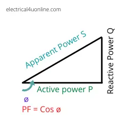
reactive power formula
We can use the power factor triangle to memorize the power factor, reactive, apparent, and active power formulas.
Single phase formula:
The formula for single-phase Reactive Power is Q = V x I x SinΦ
Where
- is the reactive power in volt-amperes reactive (VAR),
- V is the voltage in volts (V),
- I is current in amperes (A), and
- ϕ is the phase angle between the voltage and current.
Three-phase formula:
The formula for three-phase Reactive Power is Q = 1.732 x V x I x sin φ
Other shapes of the formula:
Reactive Power Q= √ (S2 – P2), While S is apparent power & P is active power.
In an AC circuit, the phase angle ϕ represents the phase difference between the voltage and current waveforms. The sine of this phase angle indicates the portion of the apparent power that is reactive.
The reactive power is the component of the apparent power that does not perform any actual work but is necessary for establishing and maintaining electromagnetic fields in reactive elements such as inductors and capacitors.
Read also My Article What is Power factor correction?
What Is The Reactive Power Compensation?
Reactive power compensation involves managing and correcting reactive power in an electrical system to enhance the power factor and overall efficiency.
The goal of reactive power compensation is to reduce the flow of reactive power and optimize the power factor, which improves the stability and performance of the power system.
It plays a vital role in maintaining stable voltage levels, minimizing power losses, and ensuring the efficient operation of the electrical grid.
By applying effective compensation techniques, utilities and industries can improve the reliability and performance of power systems, leading to greater energy efficiency and cost savings.
What Are The Advantages Of Reactive Power Compensation?
Reactive power compensation offers several advantages that contribute to the improved efficiency, stability, and performance of power systems. Some of the key benefits include:
-
Improved Power Factor: One of the primary advantages of reactive power compensation is the enhancement of the power factor. By minimizing the reactive power flow and increasing the proportion of real power in the system, the power factor is brought closer to unity (1), resulting in improved energy efficiency and reduced power losses.
-
Stable Voltage Levels: Reactive power compensation helps to stabilize voltage levels within acceptable limits, ensuring that electrical devices and equipment receive the required voltage for optimal performance. By regulating the voltage, the risk of voltage fluctuations and voltage-related issues is minimized, leading to enhanced system reliability.
-
Reduced Transmission Losses: By managing reactive power flow, the overall transmission and distribution losses in the power system can be reduced. Minimizing reactive power consumption leads to lower line losses and improved energy efficiency, ultimately resulting in cost savings and reduced environmental impact.
-
Increased Transmission Capacity: Effective reactive power compensation can improve the transmission capacity of power lines and cables. By optimizing the power factor and voltage levels, more active power can be transmitted through the existing infrastructure, enhancing the overall capacity and reliability of the power system without the need for significant upgrades.
-
Enhanced Equipment Performance: Proper reactive power compensation helps to reduce the stress on electrical equipment, including motors, transformers, and other industrial machinery. This leads to improved equipment performance, increased lifespan, and reduced maintenance costs, resulting in improved overall system reliability.
-
Compliance with Regulatory Standards: Implementing reactive power compensation enables compliance with regulatory standards related to power factor requirements. Adhering to these standards ensures the efficient and reliable operation of the power system and avoids penalties associated with poor power factor performance.
Which Is Greater Reactive or Active Power?
The comparison between reactive power (Q) and active power (P) doesn’t imply that one is necessarily greater than the other, as they represent different aspects of the power in an electrical system.
Active power (P) is the actual power that is consumed or produced and is the component of power that performs useful work. Reactive power (Q), on the other hand, is the power that does not perform any useful work but is required for the establishment of electromagnetic fields in inductive and capacitive elements.
These two components, along with the apparent power (S), form what is known as the power triangle in electrical engineering. The relationship between active power, reactive power, and apparent power is represented mathematically as:
S2=P2+Q2
Where S is the apparent power, P is the active power, and Q is the reactive power.
Although reactive power and active power differ in magnitude, both are essential for analyzing the behavior and characteristics of electrical systems. Achieving an optimal balance between them is vital to ensure the efficient and reliable operation of the power system.
For more information read my article, Apparent, Real, and Reactive Power
Do generators produce real or reactive power?
Generators produce both real power and reactive power, as they are responsible for supplying electrical energy to the power system.
The combination of these two components forms the concept of apparent power, which is the vector sum of real power (P) and reactive power (Q).
-
Real Power (P): Generators produce real power, which is the actual power that performs useful work and is consumed by electrical devices and equipment. Real power is measured in units of watts (W) or kilowatts (kW) and is responsible for tasks such as providing mechanical work, heat, or light.
-
Reactive Power (Q): Generators also produce reactive power, which is necessary for establishing and maintaining the electromagnetic fields in inductive and capacitive elements within the power system. Reactive power does not perform any actual work but is crucial for the efficient operation of devices such as motors, transformers, and other reactive loads.
The overall power output of a generator, or its apparent power (S), is the combination of both real power and reactive power, represented mathematically as:
S2=P2+Q2
Generators are designed to provide a balanced combination of real and reactive power to ensure the stable and reliable operation of the power system. Maintaining an optimal balance between these two components is essential for enhancing the efficiency and performance of the electrical grid.
Read my article for more information about Power Factor.
True / Actual Power vs. Reactive Power?
| Active power | Reactive power |
| Active power is the power that is used to do the actual work. To run a motor, light up a bulb, and charge a battery, etc. | Reactive power is not used but is employed to use the phenomenon of induction. Without reactive power, products like transformers would not be able to work. |
| It is dissipated in resistive components. | It is dissipated in reactive components. |
| It is denoted by “P”. | It is denoted by “Q”. |
| It is measured in Watts[W]. | It is measured in Volt-Amperes [VA]. |
| In AC circuits, it flows in a direction with a frequency. | In AC circuits, it does not flow but it makes the electrons move back and forth about a mean position. |
| It cannot produce magnetism. | It produces magnetism. |
| P= I2R [W] | Q= I2X [VA] |
Don’t Leave Empty-Handed!
Install my Free Android App on Google Play:
Electrical Cables Most Common Tables “Cables Tables”
And, my Electrical Calculations App “Fast Electrical Calculator”
Discover more great content by subscribing to My channel
Looking to stay ahead of the game in the world of electrical engineering? Subscribe to my YouTube channel and gain access to exclusive content you won’t find anywhere else!
The staff I recommend
(Amazon Affiliate Links to products I believe are high quality):
- Economy 120 Volt/60Hz AC Power Source – Step-Down Voltage & Frequency Converters 1800W
- UNI-T Digital Multimeter Tester UT139C
- 50-Amp Extension Cord for RV “100ft”
- Voltage Stabilizer 110/220v
- Hair Dryer “best selling“
- TOSHIBA EM131A5C-BS Countertop Microwave Ovens
Disclaimer: This contains affiliate links to Amazon products. I may earn a commission for purchases made through these links.