The connection type of resistors affects the current, voltage, and total resistance value. Let’s discuss the characteristics of connecting resistors in parallel and series
Table of Contents
Resistors in Parallel vs Series
| Properties | Resistors in Series | Resistors in Parallel |
|---|---|---|
| Current | The same current flows through all resistors | Total current is the sum of the currents through individual resistors |
| Voltage | Total voltage is the sum of individual voltages | The voltage across each resistor is the same and equal to the total voltage |
| Equivalent Resistance | Equivalent resistance is the algebraic sum of individual resistance | The reciprocal of the equivalent resistance is the sum of the reciprocals of individual resistances |
| Applications | Voltage dividers, where the input voltage is divided | Circuits requiring different resistance values for different branches or components |
What are Resistors in Parallel Combination?
Resistors in parallel combination refer to a configuration where multiple resistors are connected across the same two points, allowing multiple paths for the current to flow.
In a parallel combination, the voltage across each resistor is the same, but the current divides among the resistors according to their individual resistances.
The total resistance Req of n resistors (R1, R2, R3,…, Rn) connected in parallel can be calculated using the formula:
1/Req=1/R1+1/R2+1/R3+…+1/Rn
Where 1/Req is the sum of the reciprocals of the individual resistances.
The total resistance of a parallel combination is always smaller than the smallest individual resistance in the combination.
This is because the parallel configuration provides multiple paths for the current to flow, reducing the overall resistance.
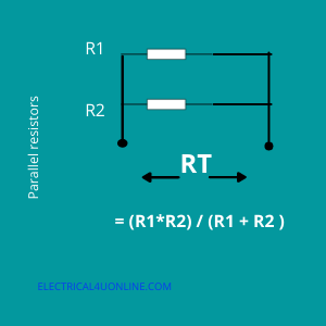
resistors in the parallel connection formula
Resistors in Parallel Formula: The equation 1/Req=1/R1+1/R2+1/R3+…+1/Rn is used to find the equivalent resistance RT of (n) number of resistors connected in parallel combination in an electrical circuit.
This equation signifies that the reciprocal of the equivalent resistance (Req) is equal to the sum of the reciprocals of the individual resistances.
Once you find the sum of the reciprocals, take the reciprocal of the sum to obtain the equivalent resistance. This formula is widely used to determine the overall resistance when multiple resistors are connected in parallel.
- In a parallel arrangement, if two resistors are equal, i.e. having the same value, the equivalent resistance RT will become equal to R/2 i.e. half of the resistance of one resistor.
- In the case of three equal resistors equivalent resistance RT will become R/3 and so on. The main point to note is that the equivalent resistance is always less than the resistance of the smallest resistor in the circuit connected in a parallel combination.
- Due to this the equivalent resistance Rt will decrease with the increase in the number of parallel resistors.
Resistors in Parallel Formula Examples
Example 1:
Assume an electrical circuit has two parallel resistors R1 = 10 Ohm & R = 20 Ohm, The equivalent resistance of the circuit will be Rt = 1/ ((1/10) + (1/20)) = 6.7 Ohm.
Example 2:
Assume R1 = 100 Ohm & R = 100 Ohm, The equivalent resistance of the circuit will be Rt = 1/((1/100) + (1/100)) = 50 Ohm.
What Are Resistors in Series?
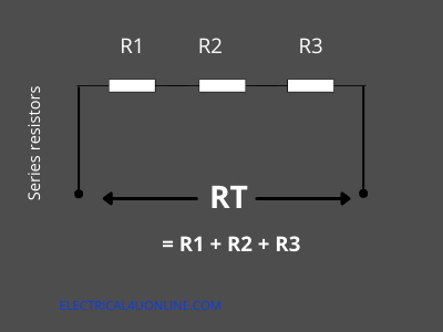
Resistors in series refer to a configuration where multiple resistors are connected end to end, forming a single path for the current to flow.
In this setup, the current passing through each resistor is the same, but the voltage across each resistor can differ, depending on their individual resistance values.
Current In Series and Parallel Resistors
Parallel Circuits:
- The current through each branch is determined by the voltage across that particular branch and the resistance of that branch (according to Ohm’s law, I=V/R).
- The total current flowing into the parallel combination is the sum of the currents flowing through the individual branches.
Series Circuits:
- The current remains the same throughout the entire circuit.
- The voltage across each component is determined by the product of the current and the resistance of that component (according to Ohm’s law, V=IR).
Resistors in Series Formula Examples
Example 1:
Assume an electrical circuit has two parallel resistors R1 = 10 Ohm & R = 20 Ohm, The equivalent resistance of the circuit will be Rt = 10 + 20 = 30 Ohm.
Example 2:
Assume R1 = 100 Ohm & R = 100 Ohm, The equivalent resistance of the circuit will be Rt = 100 + 100 = 200 Ohm.
Voltage in Series and parallel Resistors
In electrical circuits, the distribution of voltage across resistors depends on the configuration of the circuit, whether the resistors are connected in series or in parallel.
- Series Circuits:
- In a series circuit, the total voltage is the sum of the individual voltages across each resistor.
- The voltage across each resistor depends on its resistance and the current flowing through it. According to Ohm’s law, V=IR, where V is the voltage across the resistor, II is the current flowing through the resistor, and R is the resistance of the resistor.
- The total voltage of the series circuit is the sum of the voltages across each individual resistor.
- Parallel Circuits:
- In a parallel circuit, the voltage across each branch is the same. This is a consequence of the fact that all components in parallel have the same voltage drop across them.
- Each branch in a parallel circuit can have a different current, but the voltage across them remains constant.
- The total current supplied to the parallel circuit is divided among the branches according to their resistances.
Read My Other Article: What is Ohm’s Low?
Don’t Leave Empty-Handed!
Install my Free Android App on Google Play:
Electrical Cables Most Common Tables “Cables Tables”
And, my Electrical Calculations App “Fast Electrical Calculator”
Discover more great content by subscribing to My channel
Looking to stay ahead of the game in the world of electrical engineering? Subscribe to my YouTube channel and gain access to exclusive content you won’t find anywhere else!
The staff I recommend
(Amazon Affiliate Links to products I believe are high quality):
- Economy 120 Volt/60Hz AC Power Source – Step-Down Voltage & Frequency Converters 1800W
- UNI-T Digital Multimeter Tester UT139C
- 50-Amp Extension Cord for RV “100ft”
- Voltage Stabilizer 110/220v
- Hair Dryer “best selling“
- TOSHIBA EM131A5C-BS Countertop Microwave Ovens
Disclaimer: This contains affiliate links to Amazon products. I may earn a commission for purchases made through these links.