What is Ohm’s law?
Ohm’s law is a formula that describes the relationship between Current, Voltage, and resistance in electrical circuits. Its formula is Current (I) = Voltage (V) / Resistance (R)
No one can deny the importance of this law. This law is used extensively in electrical formulas and other calculations. Therefore everyone is needed to understand it deeply and apply it where requires. In this article, we will discuss this law in detail. We are going to share a little bit of history about this law. The law was first discovered by German physicist Georg Ohm.
Explanation of the law
Georg Ohm explained that when the temperature is constant. The current flowing in the electrical circuit is directly proportional to the voltage applied across it and inversely proportional to the resistance connected to the circuit. This relationship between Current, Voltage & Resistance formed the basis of Ohm’s Law.
Ohm’s law formula
Ohm’s formula is a very basic electrical formula. All electricians and electrical engineers should study and understand it. The formula is listed below.
Current (I) = Voltage (V) / Resistance (R)
Similarly, we can simplify it
I = V/R
While I is the current of the circuit in ampere, V is the voltage in volts and R is the resistance in Ohm.
Using Ohm’s Law, we can calculate the value of Voltage and Current.
The formula for Voltage Calculation:
V = I * R
Where Voltage (V) is In Volts, Current (I) in Ampere, and Resistance (R) in Ω
The formula for Resistance Calculation:
R = V/I
Hence from the equation given above, if any two values i.e. Current, Voltage, or Resistance are given. We can find the unknown value Using this Law. To find a simple relation between these values we Use Ohm’s Law Triangle.
Ohms Law Triangle
If we transpose a standard equation of Ohm law using a triangle. It gives us a combination of different values.
This triangle is used to help in memorizing the 3 forms of the law. The main triangle looks like the below one.

For finding different combinations we can use the triangle to simplify the formulas.
As we discussed above electrical circuits are made of devices. So these devices can be divided into two different categories.
Example
Assume we have an electrical circuit. In this circuit, we have a battery of 12 V, and a load of 6 Ω resistance. Calculate the current which should pass through the load.

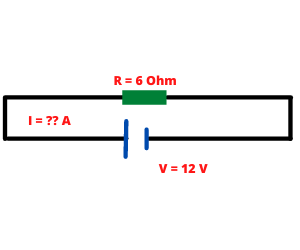
- Using Ohm’s law formula we can find the current as follows: I = V/R = 12 / 6 = 2 A
Now the same law is applicable to find the value of both resistance and voltage. Assume the same circuit with the same voltage and the current passing through the load is 2 A. We need to calculate the value of the load resistance.
- Using the same Ohm’s formula we can find the resistance as follows: R = V/I = 12 / 2 = 6 Ω.
Assume the same circuit with the same resistance and the current passing through the load is 2 A. We need to calculate the value of the battery voltage.
- Using the same Ohm’s formula we can find the voltage as follows: V = I*R = 2*6 = 12 V.
In this way, we calculated all parameters of the electrical circuit simply by using Ohm’s law formula.
Is Ohm’s law applicable to both DC and AC circuits?
Yes, Ohm’s law is applicable to both DC and AC circuits. In the DC circuit, ohm’s law is written as:
V=IR
Where R is the resistance, V is the voltage, and I is the current.
At any given branch of the circuit, the voltage V across the branch is equal to the current through the total resistance of the branch.
In the AC circuit, the confusion about ohm’s law’s application arises when we see the figure R in the mathematical formula but in the circuit, we have many other things.
These things include capacitors, inductors, phases, phase shifts, and frequency.
While in the DC circuit, we could cater to these entities by considering the voltage across these components and the concept of phases, phase shift, and frequency were totally absent.
Firstly, let us solve the problem of the R while we have C (capacitor) and L (inductor) also in the circuit. The concept of impedance exists in AC circuits.
Impedance is similar to resistance. Just like resistance, impedance also opposes the current flow. But the impedance is calculated by:
Z= sqrt (R2+ (XL2-Xc2))
, where sqrt is the square root, R is the resistance, XL is the reactance of the inductor, and XC is the reactance of the capacitor.
The reactance of the inductor or the inductance is the opposition by the inductor to the charge flow.
The reactance of the capacitor or the capacitance is the ability of a capacitor to store the charge.
As it “stores the charge”, it also provides opposition to charge flow in doing so.
So, ohm’s law in the AC circuit will be:
V=IZ
, where V is the voltage, I is current, and Z is the impedance.
But we also know that the concept of frequency exists in the AC circuit. If we want to use Ohm’s law, we need to stop the time and do our analysis at that particular time instant.
Normally, the analysis is done when the circuit achieves a steady state. You will see that when you start an analysis in the AC circuits, you describe the time instant as t=0 or t=x, etc.
So, the frequency does not arise any problems because, at any time instant, the frequency in a circuit does not change except for a complex electronics circuit that involves the practice of frequency boosting or damping.
One last issue that needs to be addressed is the phase shift. We know that in a circuit, keeping the frequency same, the phase of either the current or the voltage lags or vice versa.
In that case, too, the equation remains the same but the need for a little brief explanation arises. That is.
V=IZ
, where V=VmSin(wt), Z is the impedance, and I=ImSin(wt-θ).
Im and Vm are the magnitudes of Current and Voltage respectively. θ is defined as the phase shift.
What are the limitations of Ohm’s Law?
Some limitations of Ohm’s law are described below.
1: Temperature Limitations:
If we see the formula of Ohm’s law, there is no parameter in it that caters to the temperature. That means the change in temperature is not kept in view while using Ohm’s law.
While in a real-life scenario, constant temperature is almost impossible to attain. In a very controlled environment, it could be done, but electrical components such as wires, devices, etc. are everywhere.
When the temperature rises, the potential falls, and vice versa. But Ohm’s law does not have any factor in its formula that could show a difference in value at different temperatures. In order to satisfy Ohm’s law “temperature should be constant”.
So, the first limitation of Ohm’s law is that it does not tell the variation due to temperature.
2: Graph Analysis:
According to Ohm’s law, if we plot a graph between me on the x-axis and V on the y-axis, there should be an inclined line making an angle of 45 degrees with the x-axis.
That shows the graph is linear. But in real life, the data occurred from experimentations shows that this is not the case. If we keep increasing the value V, after a certain value, the current stops increasing.
In this case, instead of an inclined line, a straight line (almost parallel to the y-axis) is observed on the graph. It shows that the graph is not linear in real-life.
So, the second limitation is that Ohm’s law is applicable only up to a certain level of voltage.
3: Semiconductors and others:
On non-metallic conductors such as semiconductors and diodes, Ohm’s law is not applicable. Again, the reason is that these items and other non-ohmic items do not follow the 45 degrees inclined line in the V-I graph.
Why does voltage increase when the current decreases?
The answer to the first part is that we have followed the law of conservation of energy.
That means: “the energy provided to the system must be equal to the energy used by the system (or vice versa)”. “Power is the rate of energy”. The formula of power is:
P=VI
, where P is the power, V is the voltage and I is the current.
If we observe this equation written above, we can see that if we want our voltage to increase our current must decrease. Otherwise, the equation will not be satisfied.
Let us suppose we have a device that needs one horsepower (1 horsepower= 746 watts). As it is an assumption, let us say that right now at the moment, the supplied voltage is 100 Volts.
To get 746 watts, we need 7.46 Amperes. Now, we got a little practical value and say the voltage now is 220 volts.
Now to satisfy the needs of the device, we need 3.39 Amperes to get 746 watts. That is how the voltage increase affects the current.
To find out the effect of an increase in resistance, we need to see Ohm’s law. According to Ohm’s law:
V=IR
Or R=V/I.
If we see the equation written above, we can observe that if the left-hand side is increased, to satisfy the equation, 2 things could happen.
Either the voltage gets increased or the current could go down. Suppose we have a 100 kilo-ohm resistor of the lamp, connected to a 220V power supply, and a 2.2mA current is passing through this resistor.
Now let us change our device with another lamp that has a 200 kilo-ohm equipped resistor. The voltage is still the same but the current will be 1.1mA.
Similarly, if keep adding the resistances in series, the voltage across each component will keep changing after each add-up. But the current stays the same.
Why do some devices not obey ohm’s law?
There could be several reasons for a device not following ohm’s law. Devices that do not obey ohm’s law are called non-ohmic devices.
A common reason for devices not following ohm’s law is that they are non-ohmic devices. Some devices do not show linear behavior in their V-I graph. For example, in the filament lamp, the resistance changes dramatically.
The resistance of the filament lamp is very low at the start but when there has been some time passed since it started, the resistance increases too much.
At the start, the resistance has a smaller value than the normal value because the temperature of the filament bulb is too low. At lower temperatures, the electron collision is very low therefore resistance is also low.
As we know that the temperature of the filament lamp increases with time, and so does the resistance. All of this behavior plots a non-linear V-I graph. Other than the non-ohmic device, we also call the filament lamp a non-linear device.
Other examples of non-linear devices are diodes and thermistors. There are 2 reasons for a thermistor to be non-ohmic: positive temperature coefficient thermistor and negative coefficient thermistor.
In a positive coefficient thermistor, the resistance increases as the temperature increases. But in the negative coefficient, the resistance decreases, as the temperature increases.
But according to ohm’s law, the resistance must not be affected by the temperature. That’s why it is a non-ohmic device.
Is ohm’s law applicable to high voltage?
The answer is yes and no. If the circuit is purely resistive the V-I response of the circuit will be linear and thus it will be called a linear circuit.
In linear circuits, if the voltage is increased, the current also increases. So, nothing abnormal happens. If we are having a high voltage through a linear circuit, it will follow ohm’s law.
But if there are some non-linear components in the circuit, then there will be problems. Non-linear components such as diodes and transistors do not follow ohm’s law.
If the equivalent impedance of the circuit does not match a purely resistive circuit (that means if the inductive component does not cancel the capacitive components leaving the resistive part behind only), the circuit will not follow ohm’s law.
So, the problem arises only when the components are non-linear but the voltage level does not affect much.
When a bulb is turned ON, is ohm’s law applicable?
Yes, Ohm’s law is applicable when a bulb is turned on. The only condition is that the bulb is not made of a non-ohmic material.
If the bulb is made of a non-ohmic conductor, it will never follow ohm’s law. The actual realization of ohm’s law is only possible if the device is turned on.
In the laboratory tests, if you have to prove a certain conductor to be ohmic or non-ohmic, you just turn it on and start taking the readings. If it results in a linear V-I plot, it will be an ohmic device, and ohm’s law is applicable to it.
The condition for the laboratory tests is that you do not mix the values up. That means, at a particular instant, the reading of R and I are valid for only that particular V that was applied. For example, a bulb is lit-up at 240 volts.
You take is readings of current and resistance that came out to be 2mA and 120 kilo-ohms. But if you try to use these values of I and R while V is 120 volts, there will be an error in plotting the graph.
So, the instantaneous values of ohm’ law are to be measured, plotted, and used for calculations. Otherwise, the calculations will suggest that the device is non-ohmic but in real life, it will be ohmic.
Does ohm’s law hold for liquid electrolytes?
Yes, electrolytes are ohmic. Besides the fact that the electrolytes are not solid metals, they still manage to show a linear response on a V-I graph.
To prove that we need an experiment. Take an electrode of a Sodium metal and another electrode of a chlorine metal.
Dip both of them into a cell filled with the NaCl electrolyte. When a 5V battery is attached between these cells, the electronic charge starts to flow from the Cl electrode to the battery and from the battery to the Na electrode.
Now replace the 5V battery with a 9V battery. The charge flow will increase. In other words, the current will be increased.
The current is increased because more voltage is provided across the cell. We can do this experiment in a lab with a variable DC supply. Start from a 2V Dc supply and keep noting the values of the current. Then plot a graph using these values, and there will be a linear response.
Now increase the temperature from 25 degrees (room temperature) to a higher temperature while keeping the voltage constant.
There will be no change in current due to an increase in temperature. Similarly, it is unaffected by decreasing the temperature.
The whole experiment shows that the electrolyte (NaCl) is an ohmic material.
Does ohm’s law applicable to copper wire?
Yes, ohm’s law is applicable to a copper wire. In fact, copper is one of the best ohmic conductors on Earth.
A good property of an ohmic conductor is that it does not change its resistance. Copper does not show much change in resistance when the temperature is increased.
Normally, an equation is used to determine the change in the resistance due to the temperature.
Rt =R0(1+A2t)
, where “t” is the increased temperature,
A2 is a constant with a value of 4.2743 x 10⁻³ (°C⁻¹) for copper,
And R0 is the resistance at 0 degrees.
The resistance of copper at 0 degrees is 4milli-ohms. Let us say that we increase by 1 degree Celsius. Now the equation becomes.
Rt= 4m (1+4.2743 x 10⁻³ (1))
That calculates to be 0.004017, this is not a big deflection from the original value.
So, we have proved that copper is an ohmic conductor and the wires made out of copper will also follow ohm’s law.
Is ohm’s law applicable to a half-wave rectifier?
No, ohm’s law is not applicable to all half-wave rectifiers. A simple half-wave rectifier consists of a diode. Diodes are non-ohmic devices.
Diodes are non-linear devices. That means if we increase the voltage, the current due not increase with it.
That means when we plot the values taken at different magnitudes of voltages, the current may not change or change non-periodically.
That leads to non-linear plotting of the graph. Another reason is that the diodes are not purely conductors. Diodes are semiconductors.
Also, ohm’s law is not applicable to unidirectional components of the circuit. But in some special cases, ohm’s law is applicable. In the 1N4007 rectifier diode can act as an ohmic conductor when it is subjected to a very small AC input.
The diode attains a very small slope resistance in that case and it can be considered a constant resistance.
Does our body obey Ohm’s law?
Yes, our body obeys ohm’s law. According to ohm’s law, the current should increase with the increase in voltage. So, let us do an experiment.
Go to your electronics lab and grab multimeter probes and a DC power supply. Set the multimeter to the current readings and put a 2V DC across your hands.
Now keep increasing the voltage to 3,4, and so on, and keep noting the values of current after each increase in voltage.
Our body on the inside is a good conductor but the skin is a resistive material.
So, the resistance of the body may change from person to person but the increase in voltage through a particular person will show a particular increase in the current.
Does ohm’s law change for the high or low frequencies?
Yes, at higher frequencies, ohm’s law used at the higher frequency is J=sigma*E. There is no circuit in the real life that does not have any inductive or capacitive component present in it.
Inductive and capacitive components will always be there. At lower frequencies, these inductive and capacitive effects are negligible.
At higher frequencies, the relation V=IR does not apply. For example, at 4GHz frequency, V=IR cannot be realized.
So, at that much higher frequency, then we use J=sigma*E, where J is the current density, sigma is the constant of conductivity, and E is the Electric field intensity at that point. J is a function of frequency and position.
That means it changes with position and frequency. At the higher frequency, we will not have the same J at all the points on a wire.
The points distant similar from the source of the same frequency will have the same J.
So, we can say that Ohm’s law exists at lower and higher frequencies. But just the method to calculate the current changes.
How can you use ohm’s law in real-life scenarios?
We are using ohm’s law in everyday life without even knowing what er are doing. There are numerous examples of ohm’s law applications:
1: Electrical Heaters:
Electrical heaters have a metallic coil/ rod. The current through this metallic/ rod increases as the voltage is increased.
The resistance of this coil is very large. To overcome this resistance, more and more current is needed to be passed through the coil/rod.
This needs more voltage implying that an electric heater is an application of ohm’s law.
2: Domestic fans:
Domestic fans have normally a potentiometer connected in series with itself.
This potentiometer/ variable resistor/ dimmer increases or decreases the current flow through the circuit.
When we rotate it towards an increasing number, the resistance falls down and more current is flown into the circuit.
If we rotate it towards a decreasing number, the resistance adds up and the current flow in the circuit falls down.
In both cases, voltage is constant. So, the exchange of current and resistance on the cost of each other shows that this is also an application of Ohm’s law.
3: Irons, electric kettles:
Another daily-life example of the application of ohm’s law is iron. Iron has metallic rods in it that have high resistance.
This high resistance limits the current flow through themselves and heat is generated in the process. Electric kettles also work on the same principle.
4: Batteries:
Batteries also work on Ohm’s law.
What can I do with the devices that do not follow ohm’s law?
We can use ohm’s law to calculate the voltage and current of the non-ohmic devices too.
It is not that the non-ohmic devices do not fulfill the V=IR relation. It is just that the resistance changes a little bit dramatically.
Normally, we see that the resistance, being the ratio of V and I, remains a constant value. That means if we supply 240v to an ohmic device while 2mA current is flowing through this device, the resistance will be=V/I 2 kilo-ohms.
But if we voltage is decreased to 120 volts, the current will be 1mA keeping the resistance =V/I= 2 kilo-ohm. But in non-ohmic devices, resistance does not remain the same.
It changes. If I supply 240V to a non-ohmic device and the current through it is 2mA, the resistance is 2kilo-ohm.
Now I decrease the voltage to 120V and the current I measured came out to be 1.3mA rendering my resistance = V/I= 92.307 kilo-ohm.
That means the resistance has changed. But I used the same formula to calculate the resistance from my given/ measured voltages and currents.
So, the point to learn here is that the formula V=I*R is applicable for both the ohmic and non-ohmic conductors.
But the uniformity of resistance (or the constant ratio of V/I) exists in ohmic conductors only.
How many ohms should a car have?
A car battery should have very low resistance. Normally the resistance of a 12V lead-acid car battery range of resistance from 0.001 ohms to 0.02 ohms.
The internal resistance of a car battery should be very low but essential. Some people think that combining 8AA batteries in parallel gives a 12V in total.
So, taking that into an account, they can use it for starting a car. What they do not know is that the internal resistance of AA batteries is very high.
Combining the 8AA batteries in parallel will still have greater resistance than a lead-acid battery. So, the car will not be started.
Can Ohm’s law explain what does kill “current or voltage”?
It is the Current that kills. Engineers have observed from their experience that a very high voltage with a very low current, usually at an order of 5mA, does not kill.
The high voltages do not kill. It is the high current that kills. Normally, the range of fatal current is from 100mA to 200mA. Current more than 200mA will fail your heart.
But for safety purposes, some engineers suggest staying away from even a current of 20mA. We have seen a number of examples in the field where (unfortunately) people came in direct contact with high-voltage power lines (for a very short period of time like for microseconds) but they did not die.
Obviously, they had injuries but these injuries are, most of the time, non-fatal. The only reason these lucky people survived is that the current through those power lines was really low.
God forbid if the current was even 5 times the current that was flowing from those lines, the technicians would have never survived.
If we see ohm’s law, the resistances are normally used in kilo and mega-ohms. To satisfy the equation, the current has to be an order of mill, micro-amperes.
So, ohm’s law (under its breath) suggests we keep the current really low as it is fatal.
How can the ohm’s law be used to define one ohm?
If one volt of potential difference drives one ampere of current through a material, the resistance is counted to be one ohm.
No matter how we describe one ohm, the basic definition comes from the concept of Ohm’s law.
Mathematically, V=IR,
R=V/I
The equation written above gives us a ratio of voltage and current. So, we have another way to state one ohm as 1 volt per unit current is 1-ohm resistance.
That too is just another way to say the first sentence.
What are ohmic and non-ohmic devices?
This important law is not applicable to all electrical devices. It’s mainly applicable to Ohmic conductors and devices.
While it’s not applicable to non-Ohmic devices. Then what are Ohmic and non-Ohmic devices?
- Ohmic devices: A device will be called ohmic in nature if it follows ohm’s Law. i.e. the value of current will be directly proportional to Voltage and inversely to Resistance. Ohmic devices examples are cables and resistors.
- Non-Ohmic Devices: Those devices that do not follow the law of Ohm are called non-Ohmic devices. Non-Ohmic devices Example: diode, transistor, and light bulb are termed non-ohmic devices. Because in these devices the current flow mechanism is different from the ohmic devices.
Discover more great content by subscribing to My channel
Looking to stay ahead of the game in the world of electrical engineering? Subscribe to my YouTube channel and gain access to exclusive content you won’t find anywhere else!
Don’t leave empty-handed! Subscribe now.