Table of Contents
Types of Electric Motors
Electric motors come in various types, each designed for specific applications and operating conditions. Here are some common types of electric motors:
AC Motors (Alternating Current Motors):
- Induction Motors: These are the most common type of AC motors. They work on the principle of electromagnetic induction and are used in various applications, from household appliances to industrial machinery.
- Synchronous Motors: Synchronous motors rotate at a constant speed synchronized with the frequency of the AC power supply. They are often used in precision applications such as clocks and synchronous motors used in some industrial machinery.
DC Motors (Direct Current Motors):
- Brushed DC Motors: These motors use brushes and a commutator to change the direction of current flow in the rotor windings, creating rotation. They are simple and commonly used in applications like toys and small appliances.
- Brushless DC Motors (BLDC): BLDC motors use electronic commutation instead of brushes. They are more efficient and have a longer lifespan than brushed DC motors, making them suitable for applications like drones, electric vehicles, and computer cooling fans.
Stepper Motors: Stepper motors move in precise increments or steps, making them suitable for applications where precise control of position and rotation is required. They are commonly used in 3D printers, CNC machines, and robotics.
Servo Motors: Servo motors are designed for high-precision control of angular or linear positions. They are often used in industrial automation, robotics, and aerospace applications.
Linear Motors: Linear motors produce linear motion instead of rotational motion. They find use in applications like high-speed trains, conveyors, and CNC machines.
Hollow Shaft Motors: These motors have a hollow center, allowing them to be used for applications that require the passage of fluids, wires, or other materials through the motor shaft.
Universal Motors: Universal motors can operate on both AC and DC power sources. They are commonly found in power tools, vacuum cleaners, and small appliances.
Tubular Motors: Tubular motors are used in roller shutter systems, retractable awnings, and other applications where space is limited, and the motor needs to be hidden.
Hermetic Motors: These motors are designed for sealed or hermetic applications, such as refrigeration and air conditioning compressors.
Submersible Motors: Submersible motors are designed to operate underwater and are used in applications like water pumps for wells and sewage systems.
Torque Motors: Torque motors are optimized for delivering high torque at low speeds. They find use in applications such as conveyor belts and industrial machines.
Fractional Horsepower Motors: These are small motors with relatively low power ratings, often used in appliances, fans, and some automotive applications.
Solid-State Motors: These motors use semiconductor devices like transistors to control the flow of current to the motor windings, providing precise control and high efficiency.
The choice of electric motor type depends on factors such as the specific application, required performance characteristics, power source, and environmental conditions. Each type of motor has its own advantages and limitations, making it suitable for different scenarios.
Which Type Of Motor Is Used In home appliances?
Home appliances typically use a variety of electric motors depending on the specific function and requirements of the appliance. Here are some common types of motors found in home appliances:
- Induction Motors: Induction motors are widely used in home appliances such as washing machines, refrigerators, air conditioners, and fans. They are known for their reliability, durability, and ability to provide consistent performance over a long lifespan.
- Synchronous Motors: Synchronous motors are commonly used in applications where precise timing and speed control are required. They can be found in microwave ovens, turntable-style microwave plates, and some clock mechanisms.
- Universal Motors: Universal motors are versatile and can operate on both AC and DC power sources. They are often used in small kitchen appliances like blenders, food processors, and hand mixers due to their compact size and high-speed capabilities.
- Brushless DC Motors (BLDC): BLDC motors are used in various home appliances, particularly in high-efficiency applications. You can find them in some modern refrigerators, air purifiers, and small cooling fans.
- Fractional Horsepower Motors: These smaller motors are used in a wide range of appliances, including vacuum cleaners, electric can openers and hairdryers.
- Stepper Motors: Stepper motors can be found in appliances that require precise control of rotation or positioning, such as in some washing machine drum motors for optimal balance and agitation.
- Linear Motors: Linear motors may be used in appliances like dishwashers and some high-end washing machines to control the movement of racks or other components.
The choice of motor type in home appliances depends on factors like cost, energy efficiency, size constraints, and the specific function of the appliance. Manufacturers select the motor type that best meets the requirements of the appliance while ensuring cost-effectiveness and reliability.
What Are The Types Of Starter Motors Used In Automobiles?
In automobiles, starter motors are used to crank the internal combustion engine and initiate the process of internal combustion, which ultimately starts the vehicle.
Various types of starter motors have been used in automobiles over the years, but the most common types include:
- Direct Drive Starters: These starters have been a traditional choice in many vehicles. They consist of an electric motor connected directly to the engine’s flywheel or flexplate through a drive mechanism, such as a Bendix drive. When the starter motor is engaged, it spins the engine’s flywheel, turning the engine over and starting the vehicle. Direct drive starters are reliable but can be heavy and draw a relatively high amount of current.
- Reduction Gear Starters: These starters use a reduction gear mechanism to reduce the speed and increase the torque of the starter motor. The reduced speed allows for a smaller, lighter motor that draws less current while still delivering the necessary torque to crank the engine. Reduction gear starters are common in many modern vehicles because they are more energy-efficient.
- Planetary Gear Starters: Planetary gear starters are a type of reduction gear starter that uses planetary gears to achieve a reduction in speed and an increase in torque. They are compact and efficient and can be found in various vehicles.
- Permanent Magnet Starters: These starters use permanent magnets in the motor instead of traditional field coils. Permanent magnet starters are smaller, lighter, and more energy-efficient than their counterparts with field coils. They are often used in hybrid and electric vehicles.
- Gear Reduction Starters: Gear reduction starters use a planetary gear system to achieve a high torque output while maintaining a smaller size and lower current draw. They are commonly used in diesel engines and larger vehicles.
- Inertia Starters: Inertia starters rely on the principle of a spinning flywheel to store rotational energy, which can be engaged to crank the engine when starting. They are less common in modern vehicles but have been used historically.
- Soft Start Starters: Some modern starters incorporate soft start technology to gradually increase the speed of the starter motor when engaged. This reduces the stress on the engine and electrical system during startup.
The choice of starter motor type in an automobile depends on factors such as engine size, vehicle design, energy efficiency requirements, and manufacturer preferences.
In recent years, there has been a trend toward using smaller, more efficient starter motors, such as reduction gear and permanent magnet starters, to improve overall vehicle efficiency and reduce emissions.
What Type Of Electric Motor Is Used In Gas Turbine?
In gas turbine power plants, the most common type of electric motor used is the synchronous motor.
Synchronous motors are often employed for various critical functions within gas turbine power plants due to their ability to maintain a constant speed that is synchronized with the frequency of the electrical grid.
Here are some typical applications of synchronous motors in gas turbine power plants:
- Generator Drive: Gas turbines are often used to drive electrical generators to produce electricity. A synchronous generator, driven by the gas turbine, consists of a rotor that spins at a constant speed, synchronized with the grid frequency (e.g., 60 Hz in the United States). Synchronous motors are used to ensure that the generator rotor maintains this precise synchronization with the grid, allowing for efficient and stable power generation.
- Auxiliary Equipment: Gas turbine power plants have various auxiliary equipment, such as pumps, compressors, and fans, that need to operate at specific speeds. Synchronous motors can be used to drive these auxiliary components and ensure they operate at the required speed.
- Exciter Systems: Synchronous generators often require excitation systems to provide the necessary magnetic field to generate electricity. Synchronous motors are used in the exciter systems to maintain the generator’s voltage and frequency stability.
Synchronous motors are preferred in these applications because they can be precisely controlled to maintain a fixed speed, phase, and frequency, which is essential for synchronizing with the electrical grid and ensuring the stability of the power generation process.
Additionally, synchronous motors offer high efficiency and reliability, making them suitable for critical roles in gas turbine power plants.
Why do Some Motors Have Brushes and others don’t?
The presence or absence of brushes in electric motors is primarily determined by the type of motor and its design. Here’s why some motors have brushes (brushed motors) while others don’t (brushless motors):
Brushed Motors:
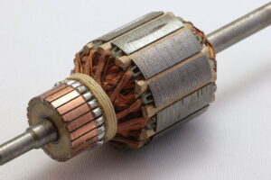
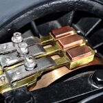
- Brushes for Commutation: In brushed motors, brushes are used for commutation. Commutation is the process of switching the direction of current flow in the motor’s armature (rotor) windings to maintain rotation. Brushes make physical contact with a commutator (a segmented cylindrical conductor attached to the rotor) and transfer electrical power to the rotor as it turns.
- Simplicity: Brushed motors are relatively simple in design and construction. They are cost-effective and have been used in a wide range of applications for many years.
- Lower Cost: Brushed motors are generally less expensive to manufacture compared to brushless motors, which can be advantageous in applications where cost is a significant factor.
- Certain Torque Characteristics: Brushed motors can provide a relatively constant level of torque across a wide range of speeds, making them suitable for some applications like power tools.
Brushless Motors:
- No Brushes for Commutation: Brushless motors, as the name suggests, do not use brushes for commutation. Instead, they use electronic controllers (often called ESCs or motor controllers) to precisely control the switching of current in the stator windings. This eliminates the need for brushes and a commutator.
- Improved Efficiency and Reliability: Brushless motors are generally more efficient and have a longer lifespan than brushed motors. Since there are no brushes to wear out, there is less maintenance required, and they generate less electrical and mechanical noise.
- Higher Power-to-Weight Ratio: Brushless motors tend to have a higher power-to-weight ratio, which means they can deliver more power for a given size and weight compared to brushed motors.
- Precise Speed Control: Brushless motors can offer precise speed control and better performance at high speeds, making them suitable for applications where accuracy and high RPMs are essential, such as drones, electric vehicles, and computer cooling fans.
- Reduced Electromagnetic Interference: Brushless motors generate less electromagnetic interference (EMI) compared to brushed motors, making them suitable for applications sensitive to EMI, such as radio communication devices and medical equipment.
The choice between brushed and brushless motors depends on the specific requirements of the application.
Brushed motors are simpler and cost-effective but may have limitations in terms of efficiency and maintenance.
Brushless motors offer higher efficiency, longer lifespan, and precise control, making them suitable for a wide range of high-performance and high-reliability applications.
Do Ac Motors Have Brushes?
Most AC motors, specifically the commonly used induction motors, do not have brushes. Induction motors operate without the need for brushes or a commutator, which are typically associated with brushed DC motors.
Here’s why AC motors, such as induction motors, do not use brushes:
- Principle of Operation: AC induction motors operate based on the principle of electromagnetic induction. They have a stationary stator winding that generates a rotating magnetic field when AC voltage is applied to it. This rotating magnetic field induces a current in the rotor, causing it to rotate. The rotor is typically a squirrel-cage design, consisting of conductive bars, and it does not have brushes or a commutator.
- No Need for Commutation: Unlike brushed DC motors, which require brushes and a commutator to change the direction of current in the rotor windings and maintain rotation, AC induction motors do not require such components. The changing magnetic field in the stator naturally induces a rotating current in the rotor, allowing for continuous and brushless operation.
- Simplicity and Reliability: The absence of brushes and commutators in AC induction motors contributes to their simplicity, reliability, and low maintenance requirements. This makes them well-suited for a wide range of industrial and residential applications, such as fans, pumps, conveyor systems, and household appliances.
While most AC motors are brushless, it’s worth noting that there are some specialized types of AC motors that use brushes, such as universal motors.
Universal motors can operate on both AC and DC power sources and use brushes and a commutator to change the direction of current flow in the rotor windings.
Universal motors are often found in small household appliances like vacuum cleaners and power tools. However, they are the exception rather than the rule when it comes to AC motors.
How To Tell If Motor Is Brushed Or Brushless?
Determining whether a motor is brushed or brushless can often be done by visually inspecting the motor and considering its characteristics. Here are some common methods to tell if a motor is brushed or brushless:
- Look for Brushes and a Commutator:
- Brushed motors have brushes, which are typically made of carbon, and a commutator, a segmented metal ring. Open the motor casing or housing and check for the presence of brushes and a commutator. If you see brushes and a commutator, it’s a brushed motor.
- Check for External Connections:
- Brushed motors often have two or more wires connected directly to the motor casing or housing. These wires are connected to the brushes and are used to supply power to the commutator. In contrast, brushless motors typically have three or more wires that lead to an external motor controller or driver, which is necessary to control the motor electronically.
- Look for Hall Effect Sensors:
- Some brushless motors, particularly those with sensorless control, may have Hall effect sensors installed on or near the motor. These sensors are used to detect the rotor’s position and are a common feature in brushless motors. If you see small sensor components near the motor, it’s likely a brushless motor.
- Check for Maintenance Requirements:
- Brushed motors require periodic maintenance because the brushes can wear out over time. If the motor’s documentation or specifications mention the need for brush replacement or maintenance, it’s likely a brushed motor. Brushless motors, on the other hand, do not have brushes and do not require this type of maintenance.
- Examine Motor Size and Weight:
- Brushless motors tend to be smaller and lighter than their brushed counterparts with similar power output. If the motor is compact and lightweight, it may be a brushless motor.
- Review Manufacturer’s Documentation:
- Consult the manufacturer’s documentation or product specifications. They often provide information about the motor type, whether it’s brushed or brushless.
- Motor Controller or Driver:
- If you have access to the motor’s control system, examine whether there is a separate motor controller or driver unit. Brushless motors require these controllers to operate, while brushed motors typically do not.
Keep in mind that while these methods can help you identify the motor type, it’s always a good practice to refer to the motor’s documentation or contact the manufacturer for confirmation, especially if you need to determine the motor type for a specific application or replacement.
What Is The Most Powerful Electric Motor Type?
The most powerful electric motor type depends on various factors, including the application, design, and technology used. In terms of sheer power output and performance, the following motor types are among the most powerful:
- Synchronous Reluctance Motors (SynRM): Synchronous reluctance motors are a type of AC motor that can deliver high power and efficiency. They are known for their ability to provide excellent performance at variable speeds and loads, making them suitable for industrial applications requiring high power output.
- Permanent Magnet Synchronous Motors (PMSM): PMSMs are high-performance AC motors that use permanent magnets in the rotor. These motors can deliver impressive power and torque output while maintaining high efficiency. PMSMs are commonly used in electric vehicles (EVs) and industrial applications.
- Induction Motors with Variable Frequency Drives (VFDs): While induction motors themselves may not be as powerful as some other types when combined with Variable Frequency Drives (VFDs), they can provide high-power output and precise control. VFDs allow for variable speed operation, which is essential in applications where power and efficiency are crucial.
- Brushless DC Motors (BLDC): BLDC motors are known for their high efficiency and power-to-weight ratio. They are used in various applications, including drones, electric vehicles, and industrial machinery, where high power output is required.
- Direct Drive Motors: Direct drive motors are a category of motors that eliminate the need for gears or other mechanical components by directly coupling the load to the motor’s output shaft. This design can result in high-power, high-torque motors used in applications like large industrial machines, wind turbines, and marine propulsion systems.
- Linear Motors: While linear motors primarily provide linear motion, they can be extremely powerful in applications that require high-force output, such as magnetic levitation (maglev) trains and some industrial machines.
It’s important to note that the most powerful electric motors are often custom-designed for specific applications, and their power output can vary widely depending on factors like size, voltage, and current.
The choice of motor type depends on the specific requirements of the application, including power output, efficiency, and other performance characteristics.
Additionally, advancements in motor technology and materials continue to push the boundaries of motor power and efficiency, leading to the development of increasingly powerful electric motors in various categories.
Don’t Leave Empty-Handed!
Install my Free Android App on Google Play:
Electrical Cables Most Common Tables “Cables Tables”
And, my Electrical Calculations App “Fast Electrical Calculator”
Discover more great content by subscribing to My channel
Looking to stay ahead of the game in the world of electrical engineering? Subscribe to my YouTube channel and gain access to exclusive content you won’t find anywhere else!
The staff I recommend
(Amazon Affiliate Links to products I believe are high quality):
- Economy 120 Volt/60Hz AC Power Source – Step-Down Voltage & Frequency Converters 1800W
- UNI-T Digital Multimeter Tester UT139C
- 50-Amp Extension Cord for RV “100ft”
- Voltage Stabilizer 110/220v
- Hair Dryer “best selling“
- TOSHIBA EM131A5C-BS Countertop Microwave Ovens
Disclaimer: This contains affiliate links to Amazon products. I may earn a commission for purchases made through these links.