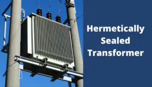
Transformer protection is not just electrical, mechanical protection also is essential! What is transformer mechanical protection? This is what I will discuss in this article!
Table of Contents
What does Transformer mechanical protection mean?
Transformer protection is generally classified as mechanical protection that is carried out by detecting operational parameters such as the transformer oil level of pressure, gas evolution, and temperature of the oil and winding.
Protecting transformers against low oil levels and high pressure inside the tank is as important as electrical protection.
Sensing these operational parameters and protecting the transformer from any abnormal condition them is known as transformer mechanical protection.
Why does the transformer need mechanical protection?
Mechanical protection is essential to protect the transformer from swear damage in case of any fault related to the transformer’s mechanical mechanism.
Identifying internal faults within the transformer using an extremely high degree of sensitivity is the main goal of Mechanical Protection.
A low oil level raises the transformer temperature decreases the life span of insulation and may lead to transformer failure. High pressure can lead to transformer tank damage.
Alongside internal faults that can occur, may result in deterioration and then accelerated aging or failure within the transformer. Therefore, it is essential to protect the transformers against these issues.
What are the mechanical protections in power transformers?
Four types of devices are used in terms of the mechanical protection of power transformers.
- Buchholz (Gas) Relay
- Pressure Relay
- Oil Level Monitor Device
- Winding Thermometer
Buchholz (Gas) Relay
Buchholz protection is a mechanical fault detection device for electric malfunctions in transformers with oil immersion.
Buchholz is a gas relay, it’s positioned in the piping between the transformer‘s main tank and the oil conservator. The conservator pipe must be inclined slightly to ensure the most reliable operation.
When the tap changer is of the on-tank (container) kind, with an oil conservator, there’s an individual Buchholz relay to the tap changer.
An average Buchholz protection consists of a pivoted floating (F) and a pivoted vane (V). The float holds one mercury switch while the vane has another mercury switch. Usually, the casing gets lined with oil, and the mercury switches are opened.
If there is a minor fault
This assumes that a minor fault happens in the transformer. Gases produced by minor faults are released from the point of fault up towards the top of the transformer.
The gas bubbles will pass through the piping until they reach the conservator. The gas bubbles will then be trapped inside the casing of Buchholz protection.
As the oil level decreases, the float (F) will flow, and the mercury switch is tilted and shuts off an alarm circuit.
When a major Fault occurs
Suppose that a major fault occurs inside the transformer either to earth or between windings or phases. Such faults rapidly result in large amounts of gases and oil vapor that cannot be escaped.
They result in a theatrical increase in pressure and displace oil. This creates an immediate flow of gas from the transformer to the conservator.
The vane (V) reacts to a high gas and oil flow through the pipe to the conservator. In this situation, the mercury switch shuts off the trip circuit.
The operation time of the trip contacts is contingent on the area where the fault occurs and the volume of the fault’s current.
Read my article about Buchholz relay for more information.
Sudden Pressure Relay
Many power transformers equipped with an on-tank type tap changer come with automatic pressure control for the tap changer’s separate oil compartment.
This safeguard detects a sudden pressure increase within the oil enclosure. If the piston’s front-end pressure is higher than the spring’s counterforce, the piston will move, activating the switches.
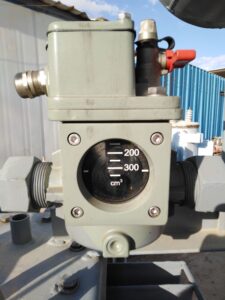
The micro switch in the switch unit is sealed hermetically and is pressurized by nitrogen gas.
The simplest type used for pressure relief devices is the commonly used frangible disk. The surge of oil triggered by a severe internal fault ruptures the disk and permits the oil to flow out quickly. Reducing and easing the pressure increase prevents an explosive rupture of the tank, causing the fire.
Using a separate tap changer, the oil enclosure could be equipped with a pressure relief device.
The device for pressure relief can be outfitted with a contacts unit to indicate circuit breaker(s) tripping circuits. The disadvantage of the frangible disk is that the oil that remains inside the tank is exposed to air following the rupture.
This is prevented by the more efficient valve for pressure relief, which is opened to allow the release of oil when the pressure is higher than the pre-adjusted limit.
If the pressure in the area is enormous, this spring-controlled valve will operate in just a few milliseconds. It can also provide quick tripping if the correct contacts are installed. The valve shuts down automatically when the internal pressure drops below a threshold.
Oil Level Monitor Device
Transformers equipped with an oil conservator(s) (expansion tank) typically come with an oil monitor.
The monitor has two contacts to signal the alarm. One is for the maximum oil level alarm, and the other is for a minimum oil level alarm.
Smaller power rating transformers have just oil level side glass indicator. This side glass shows the oil level without any alarm or shutting down signals.
The best position of the oil level indicator is the conservator tank. You should check the oil level to keep it within allowable limits.
The top-oil thermometer has an insulated bulb for a liquid thermometer inside a pocket near the top of the transformer.
The thermometer measures the temperature of the oil at the top of the transformer. The thermometer with the highest temperature could contain one to four contacts that are closed sequentially as they reach greater temperatures.
The temperature of the top oil can be significantly less than the winding temperature, particularly after a sudden increase in load. This implies that the thermometer on top of the oil is not a reliable protection against overheating.
If the rules regarding transformers’ life expectancy loss allow, tripping on top-oil temperature could be acceptable. This is in addition to the advantage of directly monitoring the oil’s temperature to ensure that it doesn’t exceed the flash temperature.
Winding Thermometer
Windings and iron core are the source of transformer temperature rise. In smaller rating transformers a temperature gauge, sometimes with alarm contacts, is used to check transformer temperature rise.
For larger-size transformers a winding thermometer reacts to the temperature at the top of the oil and the heat effect of load current. A winding thermometer produces an image showing the hot section part of the winding.
The top oil thermometer has an insulated bulb for a liquid thermometer inside a pocket near the top of the transformer.
The thermometer measures the temperature of the oil at the top of the transformer. The thermometer with the highest temperature could contain one to four contacts that are closed sequentially as they reach greater temperatures.
The temperature of the top oil can be significantly less than the winding temperature, particularly after a sudden increase in load. This implies that the thermometer on top of the oil is not a reliable protection against overheating.
If the rules regarding transformers’ life expectancy loss allow, tripping on top-oil temperature could be acceptable. This is in addition to the advantage of directly monitoring the oil’s temperature to ensure that it doesn’t exceed the flash temperature.
The top-oil temperature is measured using the same procedure that was previously described. This measurement can be further enlarged by a current signal that is in proportion to the load current inside the winding.
The current signal comes from a current transformer. This current leads to a resistor element in the central unit.
This resistor heats up, and as a result of the current flowing through it, it will, in turn, heat the measurement below, resulting in an increased indicator movement.
With four contacts, the two lower levels are employed to turn on pumps or fans to force cooling, the fourth level to trigger an alarm, and the 4th to activate breakers for load or shutting off the transformer, or both.
If a power transformer is equipped with top-oil thermometers and winding thermometers, the latter handles forced cooling control.
Don’t Leave Empty-Handed!
Install my Free Android App on Google Play:
Electrical Cables Most Common Tables “Cables Tables”
And, my Electrical Calculations App “Fast Electrical Calculator”
Discover more great content by subscribing to My channel
Looking to stay ahead of the game in the world of electrical engineering? Subscribe to my YouTube channel and gain access to exclusive content you won’t find anywhere else!
The staff I recommend
(Amazon Affiliate Links to products I believe are high quality):
- Economy 120 Volt/60Hz AC Power Source – Step-Down Voltage & Frequency Converters 1800W
- UNI-T Digital Multimeter Tester UT139C
- 50-Amp Extension Cord for RV “100ft”
- Voltage Stabilizer 110/220v
- Hair Dryer “best selling“
- TOSHIBA EM131A5C-BS Countertop Microwave Ovens
Disclaimer: This contains affiliate links to Amazon products. I may earn a commission for purchases made through these links.