Table of Contents
What is generator synchronization?
Electric generator synchronization is the process of connecting multiple generators to a common electrical bus or grid in a way that ensures their voltages, frequencies, and phases are matched.
When generators are synchronized correctly, they can be connected together to operate in parallel, supplying power to a common load or grid.
Synchronization is crucial to prevent electrical disturbances, such as voltage and frequency fluctuations, which could damage the generators and connected equipment.
Here are the key aspects of electric generator synchronization:
- Frequency Synchronization:
- Generators must operate at the same frequency to be synchronized. Frequency is the rate at which the generator produces alternating current (AC). Deviations in frequency can cause instability and damage to connected equipment.
- Voltage Synchronization:
- The voltage levels of the generators must also be synchronized. Voltage is the electrical potential difference between two points and is a critical parameter in ensuring the proper functioning of electrical equipment.
- Phase Synchronization:
- The phase angle of the generators’ output voltages must be aligned. The phase angle is the measure of the displacement in time between corresponding points on two waveforms. Synchronizing the phase ensures that the waveforms are in step with each other.
- Manual and Automatic Synchronization:
- Synchronization can be achieved manually or automatically. Manual synchronization involves adjusting the generator’s speed and voltage manually until they match the existing system. Automatic synchronization systems use control devices and sensors to detect and adjust the parameters automatically.
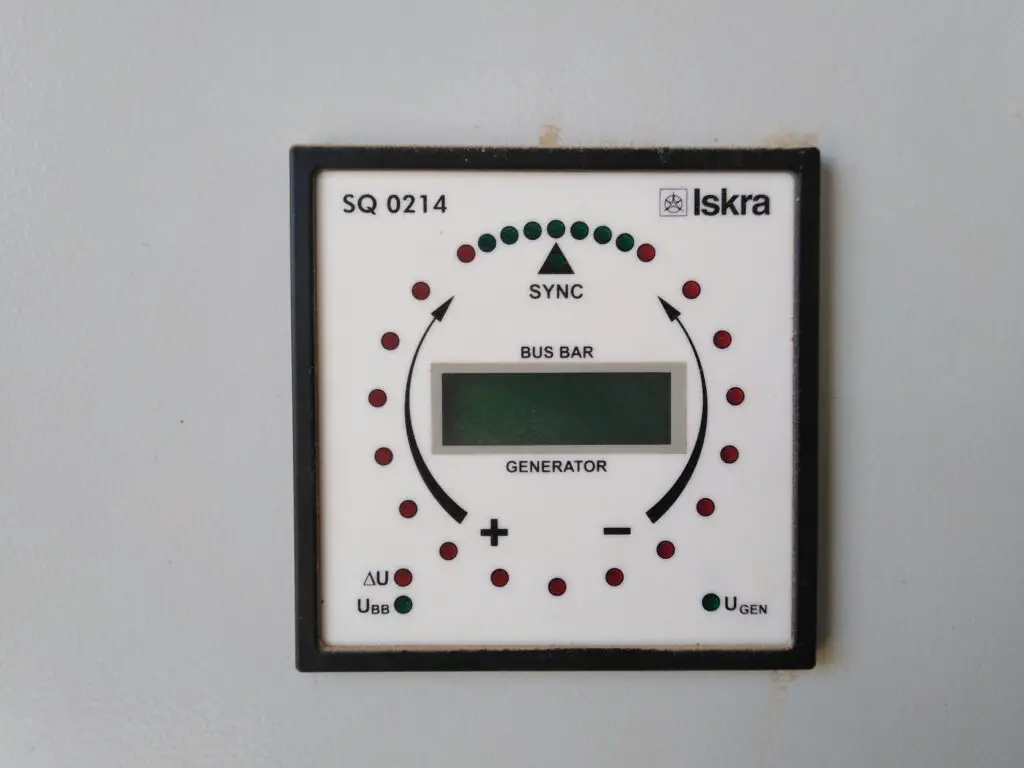
- Synchronizing Equipment:
- Synchronizing is often performed using specialized equipment, such as synchronizing relays and synchroscopes. Synchroscopes provide a visual indication of the phase difference between the generator and the system, while synchronizing relays control the generator’s circuit breaker to connect it to the grid when synchronization is achieved.
- Load Sharing:
- Once synchronized, generators can share the load in proportion to their capacities. Load sharing ensures that each generator contributes its share of power to the connected load or grid.
Proper synchronization is essential to maintain a stable and reliable power supply. It is a critical step in power plant operations, especially in situations where multiple generators need to work together to meet the demand for electrical power.
What is the condition for the parallel operation of the Generator?
For generators to operate in parallel successfully, certain conditions must be met to ensure the stability and reliability of the power system. Here are the key conditions for the parallel operation of generators:
- Frequency Synchronization:
- Generators must operate at the same frequency before they can be paralleled. Any difference in frequency can result in instability and damage to connected equipment. Synchronizing the generators ensures that they are running at the same speed and frequency.
- Voltage Synchronization:
- The voltage levels of the generators must be synchronized. Voltage synchronization is essential to prevent excessive currents and uneven distribution of power. The voltage magnitudes should be equal, and the phase angles should be aligned.
- Phase Sequence Matching:
- The phase sequence (the order in which the phases reach their peak values) of the generators must match. Mismatched phase sequences can lead to torque imbalances and potential damage to the generators.
- Voltage Magnitude Matching:
- The voltage magnitudes of the generators should be the same. If there is a significant difference in voltage levels, it can lead to unequal power sharing and may cause instability in the system.
- Phase Angle Synchronization:
- The phase angles of the generators’ output voltages must be synchronized. This ensures that the waveforms are in phase with each other, preventing sudden voltage and current changes during the connection.
- Governor and Voltage Regulator Settings:
- The governor and voltage regulator settings of each generator must be properly adjusted to control the speed and voltage within acceptable limits during parallel operation. This helps maintain stability and prevent frequency and voltage deviations.
- Properly Sized Circuit Breakers:
- Circuit breakers that connect the generators to the common bus must be appropriately sized and designed for the application. They should have the capability to handle the inrush currents during synchronization without causing damage.
- Load Sharing:
- Once synchronized, the generators should share the connected load in proportion to their capacities. Load-sharing mechanisms, such as droop control, are often used to distribute the load among the generators based on their speed and power output.
- Synchronization Devices and Equipment:
- Synchronizing relays, synchroscopes, and other monitoring devices are used to facilitate the synchronization process and ensure that the generators are connected safely and seamlessly.
Adhering to these conditions helps ensure a smooth and stable parallel operation of generators, preventing electrical disturbances and maintaining the overall reliability of the power system.
Advantages of parallel operation of generators
Parallel operation of generators offers several advantages, making it a common practice in power systems. Here are some key benefits:
- Increased Reliability:
- Parallel operation enhances the overall reliability of the power system. If one generator experiences a failure or needs maintenance, the others can continue supplying power to the load, minimizing downtime.
- Flexibility and Scalability:
- Parallel operation allows for easy integration of additional generators to meet changing power demands. This scalability provides flexibility in adapting the power generation capacity to varying load requirements.
- Improved Efficiency:
- Operating generators in parallel can improve overall efficiency. Generators can be sized to operate closer to their optimal efficiency points, leading to better fuel utilization and reduced operating costs.
- Redundancy and Backup:
- Parallel operation provides redundancy. If one generator fails or is taken offline for maintenance, the remaining generators can still supply power, ensuring continuity of service and reducing the risk of power interruptions.
- Load Sharing:
- Generators operating in parallel can share the connected load efficiently. Load-sharing mechanisms, such as droop control, distribute the load among the generators based on their capacities, preventing overloading of individual units.
- Cost Savings:
- Parallel operation allows for the use of multiple smaller generators instead of a single large generator to meet the same load. Smaller generators can be more cost-effective and easier to maintain, contributing to overall cost savings.
- Easier Maintenance:
- Maintenance tasks can be performed on one generator while others continue to supply power. This reduces the need for complete shutdowns and downtime, contributing to higher availability and reliability.
- Increased Power System Stability:
- Parallel operation helps maintain system stability by distributing the load among multiple generators. This prevents sudden disruptions in power supply and helps stabilize voltage and frequency levels.
- Better Voltage Regulation:
- Operating generators in parallel allows for better voltage regulation. Voltage regulators can be more effective when multiple generators work together to maintain steady voltage levels across the system.
- Improved Control:
- Advanced control systems can be implemented to manage the parallel operation of generators. These systems can monitor and adjust parameters such as frequency, voltage, and load sharing in real-time for optimal performance.
- Grid Support:
- Generators operating in parallel can provide support to the grid, contributing to system stability and reliability. They can respond to changes in demand and help manage grid disturbances.
While there are clear advantages to parallel operation, it is crucial to adhere to synchronization and operational guidelines to ensure the safe and reliable functioning of the generators and the power system as a whole.
What is a synchronization panel?
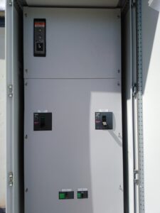
Synchronization panels are typically developed and utilized to meet the power system’s requirements.
They work both manually and also with an automatic function of synchronizing two or more breakers or generators.
They are commonly used in the process of synchronizing generators, as well as they are also used to provide multiplex solutions.
These load-sharing units continually check the load. During low demand, one or two generators may be closed to conserve fuel. The third and second generators will be restarted, then synchronized, and connected to load when demand increases.
Automatic and manual synchronization
Automatic and manual synchronization are two methods used to synchronize generators with an electrical grid or with each other when connecting in parallel.
Synchronization is a crucial step to ensure that the generators share the load seamlessly without causing disturbances in voltage, frequency, or phase. Here’s an explanation of both automatic and manual synchronization:
- Manual Synchronization:
- Process:
- In manual synchronization, the operator or engineer manually adjusts the speed and voltage of the incoming generator to match those of the system or grid.
- The operator typically uses synchronizing relays, synchroscopes, and other monitoring devices to determine when the generator’s frequency, voltage, and phase angle are in synchronization with the existing system.
- Once the parameters are matched, the operator closes the generator’s circuit breaker to connect it to the grid or common bus.
- Advantages:
- Manual synchronization provides direct control to the operator, allowing them to carefully monitor and adjust the synchronization process.
- It is often used in situations where automatic systems may not be available or may not be the preferred method due to specific operational requirements.
- Disadvantages:
- Manual synchronization relies on the skill and experience of the operator, which can introduce a human error factor.
- It may take longer to synchronize compared to automatic methods, and the process might not be as precise.
- Process:
- Automatic Synchronization:
- Process:
- Automatic synchronization systems use electronic devices and control algorithms to monitor and adjust the generator’s parameters automatically.
- Sensors and relays continuously monitor the generator’s frequency, voltage, and phase angle, comparing them to the values of the system or grid.
- The automatic system adjusts the generator’s speed and voltage to bring them into synchronization with the grid or other generators.
- Once synchronization is achieved, the automatic system closes the generator’s circuit breaker.
- Advantages:
- Automatic synchronization is faster and more precise than manual synchronization, reducing the risk of human error.
- It allows for quicker response to changes in the grid conditions, ensuring a seamless connection of the generator to the system.
- Disadvantages:
- Automatic synchronization systems may require additional equipment and maintenance compared to manual methods.
- They might be more complex, requiring careful calibration and periodic checks to ensure accurate operation.
- Process:
In practice, both manual and automatic synchronization methods are used based on the specific requirements of the power system, the available technology, and the preferences of the operators.
Some systems may employ a combination of both methods, allowing operators to choose the most suitable approach based on the circumstances.
Which is better connecting a generator or two in parallel?
Whether connecting generators in parallel manually or automatically is considered “better” depends on various factors, including the specific requirements of the power system, safety considerations, ease of operation, and the available technology. Both manual and automatic synchronization methods have their advantages and disadvantages.
Manual Synchronization:
- Advantages:
- Direct control: Operators have direct control over the synchronization process, allowing them to carefully monitor and adjust parameters.
- Useful in specific situations: Manual synchronization may be preferred in certain situations where precise control is necessary.
- Disadvantages:
- Human error: There is a potential for human error during the manual synchronization process.
- Time-consuming: Manual synchronization can take longer compared to automatic methods, and the process may not be as fast or precise.
Automatic Synchronization:
- Advantages:
- Speed and precision: Automatic synchronization is generally faster and more precise, reducing the risk of human error.
- Quicker response: Automatic systems can respond quickly to changes in grid conditions.
- Disadvantages:
- Complexity: Automatic synchronization systems may be more complex, requiring additional equipment and maintenance.
- Calibration: They require careful calibration and periodic checks to ensure accurate operation.
Choosing Between Manual and Automatic Synchronization:
The choice between manual and automatic synchronization depends on the specific requirements and constraints of the power system. Here are some considerations:
- System Complexity:
- For simpler systems or situations where precise control is not critical, manual synchronization may be sufficient.
- Automatic synchronization is often preferred for larger and more complex systems where rapid and accurate synchronization is essential.
- Operator Skill and Training:
- Manual synchronization requires skilled operators with experience in managing the synchronization process.
- Automatic synchronization may be more suitable in situations where the operator’s skill level is a concern or where a quicker response is needed.
- Safety:
- Automatic synchronization systems can enhance safety by reducing the risk of human error during the synchronization process.
- In critical applications or where safety is a top priority, automatic synchronization may be preferred.
- Cost and Resources:
- Automatic synchronization systems may involve higher upfront costs and maintenance requirements.
- Manual synchronization could be more cost-effective in simpler systems with trained operators.
In many modern power systems, a combination of manual and automatic synchronization may be implemented, allowing operators to choose the method based on the specific circumstances.
Ultimately, the choice should be based on a thorough assessment of the system requirements, operator expertise, and safety considerations.
Don’t Leave Empty-Handed!
Install my Free Android App on Google Play:
Electrical Cables Most Common Tables “Cables Tables”
And, my Electrical Calculations App “Fast Electrical Calculator”
Discover more great content by subscribing to My channel
Looking to stay ahead of the game in the world of electrical engineering? Subscribe to my YouTube channel and gain access to exclusive content you won’t find anywhere else!
The staff I recommend
(Amazon Affiliate Links to products I believe are high quality):
- Economy 120 Volt/60Hz AC Power Source – Step-Down Voltage & Frequency Converters 1800W
- UNI-T Digital Multimeter Tester UT139C
- 50-Amp Extension Cord for RV “100ft”
- Voltage Stabilizer 110/220v
- Hair Dryer “best selling“
- TOSHIBA EM131A5C-BS Countertop Microwave Ovens
Disclaimer: This contains affiliate links to Amazon products. I may earn a commission for purchases made through these links.