
Table of Contents
What is galvanic isolation?
Galvanic isolation is a technique used in electrical and electronic systems to prevent unwanted current flow between different system parts while still allowing for signal or power transfer.
The primary purpose of galvanic isolation is to ensure electrical safety, protect sensitive components, and eliminate the risk of ground loops.
The term “galvanic” refers to the use of a galvanic cell or a device that converts chemical energy into electrical energy.
In the context of isolation, it means breaking the electrical connection between two circuits by using a barrier that does not conduct electrical current. This barrier is often a transformer, optocoupler, or other isolation device.
Common methods of achieving galvanic isolation include:
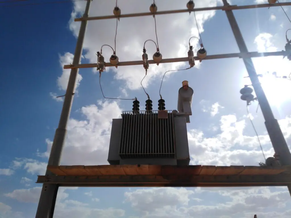
- Transformers: These devices use electromagnetic induction to transfer electrical energy between two or more coils without a direct electrical connection. Transformers are commonly used for isolating power supplies and audio signals.
- Optocouplers (Opto-isolators): These components use light to transmit signals across an isolation barrier. An optocoupler typically consists of a light-emitting diode (LED) on one side and a photodetector (like a photodiode or phototransistor) on the other side. When the LED is energized, it emits light that is detected by the photodetector, allowing signal transfer without a direct electrical connection.
- Capacitive Coupling: In some cases, capacitors are used to couple AC signals while blocking DC currents. This method is less common for high-voltage applications but is suitable for low-voltage signal isolation.
- Magnetic Coupling: Magnetic coupling, similar to transformers, is used to transmit signals without a direct electrical connection. It involves the use of inductors or coils to create a magnetic field that induces a voltage in a nearby coil.
Galvanic isolation is crucial in various applications, including power supplies, communication systems, and medical devices.
By implementing galvanic isolation, the risk of electrical shock, ground loops, and damage to sensitive components can be minimized, enhancing the safety and reliability of electronic systems.
For more information about capacitors read my detailed article here.
How does the Transformer provide galvanic isolation?
In the context of electrical engineering, an electromagnetic transformer is a device that uses electromagnetic induction to transfer electrical energy between two or more coils of wire without a direct electrical connection. This principle is based on Faraday’s law of electromagnetic induction.
Here’s how an electromagnetic transformer provides galvanic isolation:
- Basic Structure: A transformer consists of two coils of wire, known as the primary and secondary windings. These coils are electrically isolated from each other.
- Mutual Induction: When an alternating current (AC) flows through the primary winding, it generates a changing magnetic field around it. This changing magnetic field induces a voltage in the secondary winding through the principle of mutual induction.
- Isolation: Since the primary and secondary windings are not electrically connected, there is no direct electrical path between them. The electrical energy is transferred from the primary to the secondary side solely through the magnetic field.
- Voltage Transformation: The turns ratio of the primary and secondary windings determines the voltage transformation between the input and output. If the turns ratio is, for example, 1:2, a voltage applied to the primary winding will result in twice that voltage across the secondary winding.
By this electromagnetic induction process, transformers provide galvanic isolation between the input and output sides.
This isolation is crucial for safety, as it helps prevent the transfer of potentially harmful voltages or currents from one side to the other.
Transformers are commonly used for isolating power supplies, stepping up or stepping down voltage levels, and eliminating ground loops in various electrical systems.
Where and why galvanic transformers are used?
Let me clarify the use of transformers and galvanic isolation devices separately:
- Transformers:
- Power Distribution: Transformers are widely used in power distribution networks to step up or step down voltage levels for efficient transmission of electrical power.
- Power Supplies: They are used in electronic devices to convert voltages for power supply purposes.
- Isolation: Transformers provide galvanic isolation, as mentioned earlier, preventing direct electrical connections between the primary and secondary sides.
- Galvanic Isolation Devices:
- Medical Devices: In medical equipment, where patient safety is critical, galvanic isolation is often employed to prevent the risk of electrical shocks.
- Industrial Controls: Galvanic isolation is used in industrial automation systems to protect sensitive equipment and ensure reliable operation.
- Communication Systems: Isolation is crucial in communication systems to prevent ground loops and enhance signal integrity.
- Data Transmission: Galvanic isolation is employed in data communication interfaces to protect equipment and improve signal quality.
In summary, transformers play a vital role in various applications, including power distribution and electronic devices, and they inherently provide galvanic isolation.
Galvanic isolation devices, on the other hand, are specifically designed to ensure isolation in applications where electrical separation is critical for safety or performance reasons.
Why isolation transformers are used in UPS?
Isolation transformers are commonly used in Uninterruptible Power Supply (UPS) systems for several important reasons:
- Electrical Isolation:
- Safety: Isolation transformers provide a high degree of electrical isolation between the input and output sides. This isolation helps prevent electrical shock hazards and protects both the connected equipment and personnel.
- Noise and Surge Protection:
- Surge Protection: Isolation transformers can help protect connected devices from voltage spikes and surges by limiting the transmission of these disturbances from the input to the output side.
- Common Mode Noise: They are effective at attenuating common mode noise, which is unwanted electrical noise that occurs in the same direction on both the line and neutral conductors. This can be important for sensitive electronic equipment.
- Ground Loop Elimination:
- Preventing Ground Loops: Isolation transformers help eliminate ground loops, which can occur when there are multiple paths to ground in a system. Ground loops can introduce noise and cause interference in electronic equipment. The isolation provided by the transformer breaks the ground loop paths.
- Voltage Regulation:
- Stabilizing Output Voltage: Isolation transformers contribute to voltage regulation by providing a consistent output voltage, even if there are fluctuations or disturbances in the input power. This helps maintain a stable power supply to connected equipment.
- Compatibility with Sensitive Equipment:
- Sensitive Electronics: Some electronic equipment, especially in data centers or critical systems, may be sensitive to variations in power quality. Isolation transformers help ensure a clean and stable power supply, reducing the risk of damage or malfunctions in sensitive devices.
- Compliance with Standards:
- Regulatory Compliance: In some cases, regulatory standards or specific application requirements may mandate the use of isolation transformers in UPS systems to meet safety and performance criteria.
In summary, the use of isolation transformers in UPS systems provides a layer of protection against electrical hazards, improves power quality, and ensures the reliable and safe operation of connected equipment, especially in applications where a clean and stable power supply is critical.
Are all transformers the isolation transformers?
No, not all transformers are isolation transformers. While all transformers operate based on the principles of electromagnetic induction, isolation transformers have a specific design and purpose to provide electrical isolation between their input and output sides.
The term “isolation transformer” typically refers to transformers designed with the primary intention of isolating the input and output electrically.
Here are some key characteristics of isolation transformers:
- Electrical Isolation: The primary function of an isolation transformer is to provide a high level of electrical isolation between the input and output windings. This helps prevent direct electrical contact and minimizes the risk of electric shock.
- Separate Grounding: Isolation transformers often have separate grounding for the primary and secondary sides, helping to eliminate ground loops and reduce the risk of interference or noise in connected equipment.
- No Common Connection: Unlike some transformers used for voltage transformation, isolation transformers do not have a direct electrical connection (common winding) between the primary and secondary sides.
- Applications: Isolation transformers are commonly used in applications where electrical isolation is crucial for safety and equipment protection. This includes medical equipment, industrial machinery, sensitive electronic devices, and UPS systems.
If you need more details about step-up and step-down transformers read my article.
Why are Isolation transformers safer?
Isolation transformers are considered safer in certain applications for several reasons, primarily due to their ability to provide electrical isolation between the input and output sides. Here are some key factors contributing to the safety advantages of isolation transformers:
- Prevention of Electrical Shock:
- Physical Isolation: Isolation transformers physically separate the primary and secondary windings, preventing direct electrical contact between them. This reduces the risk of electrical shock to personnel and protects against accidental contact with live electrical components.
- Ground Loop Elimination:
- Separate Grounding: Isolation transformers often have separate grounding for the primary and secondary sides. This helps eliminate ground loops, which can be a source of electrical interference and safety hazards in certain applications.
- Surge and Noise Protection:
- Surge Isolation: Isolation transformers can protect against voltage spikes and surges, limiting the transmission of these disturbances from the input to the output side.
- Common Mode Noise Rejection: They are effective at attenuating common mode noise, which is noise that occurs in the same direction on both the line and neutral conductors. This is important for sensitive electronic equipment.
- Stability and Voltage Regulation:
- Consistent Output Voltage: Isolation transformers contribute to voltage regulation by providing a consistent output voltage, even in the presence of fluctuations or disturbances in the input power. This stability is important for sensitive electronic devices.
- Reduction of Interference:
- Electromagnetic Interference (EMI): Isolation transformers can help reduce electromagnetic interference, providing a cleaner and more stable power supply to connected equipment.
- Compliance with Safety Standards:
- Meeting Regulatory Requirements: In certain industries and applications, safety standards may require the use of isolation transformers to comply with specific safety regulations and standards.
- Protection for Sensitive Equipment:
- Equipment Compatibility: Isolation transformers are commonly used in applications where connected equipment is sensitive to power quality variations. The isolation helps protect this equipment from potential damage or malfunctions.
It’s important to note that while isolation transformers provide additional safety benefits, their use may not be universally required in all situations.
The level of safety provided depends on the specific application and the potential risks associated with electrical hazards.
Isolation transformers are particularly valuable in environments where personnel safety and equipment protection are critical considerations.
The difference between a transformer and an isolation
transformer
A transformer is a generic term that refers to a device used to transfer electrical energy between two or more circuits through electromagnetic induction.
An isolation transformer, on the other hand, is a specific type of transformer designed to provide electrical isolation between its input and output sides.
Let’s explore the key differences between a transformer in general and an isolation transformer:
Transformer:
- Voltage Transformation:
- Purpose: Transformers are commonly used for voltage transformation, either stepping up or stepping down the voltage levels between the primary and secondary windings.
- Design: Transformers can have various designs, and their primary function is to transfer electrical energy efficiently.
- Applications:
- Diverse Uses: Transformers are used in power distribution networks, electronic devices, audio equipment, and many other applications where voltage transformation is required.
- Electrical Connection:
- Direct Connection: In standard transformers, there is a direct electrical connection between the primary and secondary windings. The voltage induced in the secondary winding is directly proportional to the turns ratio.
Isolation Transformer:
- Electrical Isolation:
- Purpose: The primary purpose of an isolation transformer is to provide a high degree of electrical isolation between the input and output sides.
- Design: Isolation transformers are designed to physically and electrically separate the primary and secondary windings, minimizing direct electrical contact.
- Safety Features:
- Preventing Shock: Isolation transformers are safer for personnel as they help prevent electrical shock by breaking the electrical connection between the input and output.
- Applications:
- Safety-Critical Applications: Isolation transformers are commonly used in applications where electrical safety is crucial, such as medical equipment, industrial machinery, and UPS systems.
- Grounding:
- Separate Grounding: Isolation transformers often have separate grounding for the primary and secondary sides, helping to eliminate ground loops and enhance safety.
- Surge and Noise Protection:
- Surge Isolation: Isolation transformers can provide some level of protection against voltage spikes and surges.
- Noise Rejection: They are effective at attenuating common mode noise, enhancing the quality of the power supply to connected equipment.
In summary, while all isolation transformers are transformers, not all transformers are isolation transformers.
The term “isolation transformer” specifically denotes a transformer designed to address safety concerns by providing electrical isolation, making it particularly suitable for applications where personnel safety and equipment protection are critical.
Install my Free Android App on Google Play:
Electrical Cables Most Common Tables
And, my Electrical Calculations App “”
Discover more great content by subscribing to My channel
Looking to stay ahead of the game in the world of electrical engineering? Subscribe to my YouTube channel and gain access to exclusive content you won’t find anywhere else!
The staff I recommend
(Amazon Affiliate Links to products I believe are high quality):
- Economy 120 Volt/60Hz AC Power Source – Step-Down Voltage & Frequency Converters 1800W
- UNI-T Digital Multimeter Tester UT139C
- 50-Amp Extension Cord for RV “100ft”
- Voltage Stabilizer 110/220v
- Hair Dryer “best selling“
- TOSHIBA EM131A5C-BS Countertop Microwave Ovens
Disclaimer: This contains affiliate links to Amazon products. I may earn a commission for purchases made through these links.