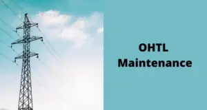
I encounter overhead power lines frequently during my travels, and as an electrical engineer, my attention is naturally drawn to them.
Additionally, recognizing the numerous inquiries beginners often have about overhead power lines, I aim to address six common questions in this article. Let’s begin.
Table of Contents
Are Overhead Power Lines AC Or DC?
Overhead power lines typically carry alternating current (AC) rather than direct current (DC). AC is commonly used for long-distance power transmission because it can be easily transformed to different voltage levels using transformers, which facilitates efficient power distribution.
AC power can be generated, transmitted, and distributed more efficiently over long distances compared to DC power.
While AC is commonly used for power transmission, direct current (DC) is sometimes used in specific applications such as high-voltage direct current (HVDC) transmission lines for very long-distance power transmission or in certain specialized systems.
However, for most overhead power lines, especially those in urban and suburban areas, alternating current is the standard.
Why are Overhead Power Lines Not Insulated?
Overhead power lines are not typically insulated in the same way that electrical wires inside your home are insulated. The main reasons for this include cost, practicality, and efficiency.
- Cost: Insulating overhead power lines with traditional insulation materials, like the rubber or plastic insulation used in household wiring, would significantly increase the cost of manufacturing and installing these lines. The vast distances covered by many power lines make the cost of insulating the entire length prohibitive.
- Practicality: The sheer length of many overhead power lines, especially those used for long-distance transmission, makes it impractical to cover them entirely with insulation. The weight of the insulation and the associated support structures would be challenging to manage over such long spans.
- Efficiency: Overhead power lines transmit electricity at high voltages. This high voltage is necessary to minimize energy losses during transmission. If the lines were insulated, it would increase the capacitance between the conductors and the surrounding environment, leading to increased energy losses in the form of heat.
Instead of insulating the entire power line, the focus is on keeping the conductors at a safe distance from each other and from the ground or other objects to prevent electrical arcing and ensure safety. Additionally, the air surrounding the conductors acts as a natural insulator, helping to contain the electrical current within the lines.
It’s important to note that some types of power lines, especially those at lower voltages and in specific situations, may have partial insulation or additional protective measures in place. However, for high-voltage transmission lines that span long distances, complete insulation is not a practical or cost-effective solution.
What Are Voltage Levels of Overhead Power Lines?
Overhead power lines operate at various voltage levels, depending on their purpose and the distance they need to cover. The voltage levels can be broadly categorized into three main classes:
- Low Voltage Lines (LV): These are typically distribution lines that carry lower voltages to residential, commercial, and industrial areas. In many countries, low-voltage lines operate at voltages below 1,000 volts (e.g., 120/240 volts in residential areas).
- Medium Voltage Lines (MV): Medium voltage lines are used for distributing power within a local area or community. They typically operate at voltages ranging from 1,000 volts to around 33,000 volts. Common medium voltage levels include 4,160 volts and 13,800 volts.
- High Voltage Lines (HV): High voltage lines are used for long-distance transmission of electrical power. These lines operate at higher voltages to minimize energy losses during transmission. High voltage lines can range from about 44,000 volts (44 kV) to several hundred thousand volts (up to 765 kV or more).
There are also Extra High Voltage (EHV) and Ultra High Voltage (UHV) lines, which operate at voltages exceeding 100 kV and 800 kV, respectively. These lines are often used for very long-distance transmission of power.
The specific voltage levels can vary between countries and regions, and advancements in technology may lead to changes in typical voltage levels over time. The mentioned voltage levels provide a general overview of the classifications for overhead power lines.
What Are OHTL Conductors Made Of?
Overhead High-Tension Lines (OHTL) conductors are typically made of aluminum or aluminum alloy, though steel is sometimes used. The choice of material depends on various factors including the specific application, voltage level, and engineering considerations. Here are the common materials used:
- Aluminum: Aluminum is a popular choice for OHTL conductors due to its lightweight nature and good conductivity. Aluminum conductors are often used in transmission lines where low weight is essential to reduce the load on support structures such as towers. The lightweight property of aluminum makes it easier and more cost-effective to install and maintain.
- Aluminum Alloy: Some conductors are made from aluminum alloys, which offer improved mechanical strength compared to pure aluminum. Aluminum alloys provide a good balance between weight, conductivity, and mechanical properties.
- Steel-Reinforced Aluminum (ACSR): ACSR (Aluminum Conductor Steel Reinforced) is a type of conductor that combines aluminum and steel. The core of the conductor is made of steel, which provides strength, while the outer layer is made of aluminum to enhance conductivity. ACSR conductors are commonly used in medium and high-voltage transmission lines.
The choice of conductor material is influenced by factors such as the distance the power line needs to span, the required conductivity, mechanical strength, and environmental conditions. Different types of conductors are engineered to meet specific requirements for optimal performance in various applications.
What Are Power Line Insulators Made Of?
Power line insulators are crucial components in overhead power line systems. They are used to support and insulate the conductors from the structures that hold them, preventing electrical current from flowing into the supporting structures.
Insulators are typically made of materials with high electrical resistance and good mechanical strength. The most common materials for power line insulators include:
- Porcelain: Traditional power line insulators have been made primarily from porcelain, which is a type of ceramic material. Porcelain insulators are known for their high mechanical strength, resistance to environmental factors such as UV radiation and pollution, and excellent electrical insulating properties.
- Glass: Similar to porcelain, glass insulators are also used in power lines. They offer good electrical insulation and resistance to environmental conditions. Glass insulators are often used in less demanding applications compared to porcelain.
- Polymer (Composite) Insulators: Modern power lines also use insulators made from polymer materials, often referred to as composite insulators. These insulators are composed of fiberglass-reinforced epoxy or silicone rubber. Polymer insulators are lighter than porcelain or glass insulators, making them easier to handle and install. They also exhibit good resistance to pollution and are less prone to breakage.
The choice of insulator material depends on various factors, including the voltage level of the power line, environmental conditions, and specific application requirements.
Different types of insulators are designed to meet the needs of different power transmission and distribution systems.
Why Does Rain Not Cause Overhead Power Lines Short Circuit?
Rain by itself typically does not cause short circuits on overhead power lines. Overhead power lines are designed and constructed with consideration for various weather conditions, including rain. Here are a few reasons why rain does not usually lead to short circuits on power lines:
- Insulation: The conductors used in overhead power lines are coated with insulating materials, such as polymers or other non-conductive substances. These insulating materials prevent the flow of electricity from the conductors to the surrounding environment, even when they are wet.
- Spacing: The conductors on power lines are spaced apart at a safe distance. This spacing is designed to prevent arcing or unintentional contact between the conductors, even in rainy conditions. Adequate spacing helps maintain the integrity of the electrical insulation.
- Design for Outdoor Conditions: Overhead power lines are designed to withstand various environmental factors, including rain, wind, and temperature variations. The materials used in the construction of power lines are selected to be durable and resistant to weather-related degradation.
While rain itself may not cause short circuits, severe weather conditions like storms, high winds, or ice accumulation can pose challenges to power lines. For example, heavy ice buildup on power lines can increase the weight of the conductors, potentially leading to structural issues or breakages.
To further enhance the reliability of power transmission systems in adverse weather conditions, engineers may implement additional measures, such as the use of corona rings or devices to reduce the risk of corona discharge (a phenomenon associated with high-voltage systems that can occur in damp conditions) and proper grounding to protect against lightning strikes.
It’s important to note that while rain may not directly cause short circuits, a combination of factors such as wind, ice, or other extreme weather conditions can contribute to power line issues.
Regular maintenance and inspections are conducted to ensure the continued safe and reliable operation of overhead power lines in various environmental conditions.
For more details about short circuits read my article here.
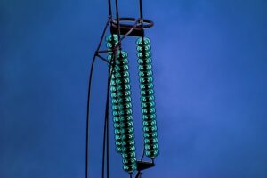
Why Do OHTL Insulators Have Skirting?
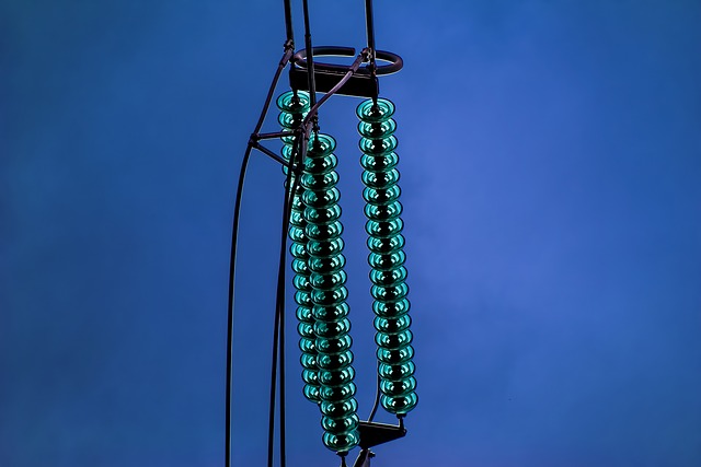
Overhead High-Tension Line (OHTL) insulators often have skirts or sheds as part of their design. These skirts serve a specific purpose related to the performance and reliability of the insulator in various weather conditions. Here are the main reasons why OHTL insulators have skirts:
- Pollution and Contamination Resistance: Skirts are designed to provide an additional layer of protection against pollution and contamination. In areas where the atmosphere contains pollutants, such as industrial areas or coastal regions, contaminants can be deposited on the insulator surface. The skirts help to shed or repel these contaminants, preventing the formation of a conductive layer that could compromise the insulator’s performance.
- Flashover Prevention: Flashover is a phenomenon where electricity arcs across the surface of an insulator, usually due to contamination or the presence of conductive deposits. Skirts play a crucial role in preventing flashovers by reducing the likelihood of contaminants accumulating on the surface of the insulator. The shedding action helps to break the continuity of the conductive path and maintain the insulator’s electrical integrity.
- Rain and Water Shedding: Skirts are also effective in shedding rainwater. By preventing the accumulation of water on the insulator surface, skirts reduce the risk of leakage currents and flashovers. Efficient water shedding is particularly important during rainy conditions to maintain the insulator’s insulating properties.
- Corona Control: Skirts can contribute to corona control. Corona discharge, which can occur in high-voltage systems, is associated with energy losses and audible noise. Skirts help manage the electric field around the insulator, minimizing the risk of corona discharge and associated issues.
In summary, the skirts on OHTL insulators are designed to enhance the insulator’s performance in challenging environmental conditions.
They play a critical role in preventing contamination, reducing the risk of flashovers, and maintaining the insulator’s insulating properties, ultimately contributing to the reliability and efficiency of overhead power transmission systems.
what are the orange balls on power lines?
The orange balls on power lines are often referred to as marker balls or visibility balls. These balls are placed on power lines to enhance the visibility of the lines, particularly for low-flying aircraft.
They are usually bright orange and may be attached at regular intervals along the length of the power lines.
The primary purposes of these orange balls include:
- Aviation Safety: The bright color of the balls makes the power lines more visible to pilots, especially during low-visibility conditions, such as fog, mist, or low light. They serve as a visual warning to pilots, helping them avoid collisions with the power lines.
- Prevention of Accidents: Making power lines more visible is crucial for preventing accidents involving aircraft, including helicopters and small planes. The balls help pilots identify the presence and location of power lines to navigate safely around them.
- Regulatory Compliance: In many regions, aviation authorities and power utility regulations require the use of marker balls on power lines to enhance safety and reduce the risk of aviation-related accidents.
The balls are typically made of materials that can withstand weather conditions and environmental exposure. They are often attached to the power lines by a tether, allowing them to move freely in the wind. The movement helps maintain visibility and prevents the balls from accumulating ice or debris.
While orange is a common color for these marker balls, other colors, such as white or red, may also be used depending on regional regulations and specific visibility requirements. The use of these balls is just one of several measures taken to enhance the safety of power lines, particularly in areas with significant air traffic.
Install my Free Android App on Google Play:
Electrical Cables Most Common Tables
And, my Electrical Calculations App “”
Discover more great content by subscribing to My channel
Looking to stay ahead of the game in the world of electrical engineering? Subscribe to my YouTube channel and gain access to exclusive content you won’t find anywhere else!
The staff I recommend
(Amazon Affiliate Links to products I believe are high quality):
- Economy 120 Volt/60Hz AC Power Source – Step-Down Voltage & Frequency Converters 1800W
- UNI-T Digital Multimeter Tester UT139C
- 50-Amp Extension Cord for RV “100ft”
- Voltage Stabilizer 110/220v
- Hair Dryer “best selling“
- TOSHIBA EM131A5C-BS Countertop Microwave Ovens
Disclaimer: This contains affiliate links to Amazon products. I may earn a commission for purchases made through these links.